1 695 105 790 2010-05-04| Robert Bosch GmbH
32 | TCE 4540 | Initial commissioningen
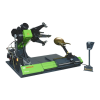
3. L
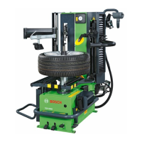
ift the TCE 4540 with a lift crane and install it in
the designed area respecting minimum distances as
shown in the picture.
652061-04_Mi
500
1850
1880
500
1700
i For safe and ergonomic use of the TCE 4540 it is
recommended to install the equipment at a minimum
distance of 500 mm from the surrounding walls.
Warning - tilting danger!
During tire inflation considerable forces are
exerted.
The TCE 4540 has to be fixed in at least 3
points on the floor (screw holes see chap.
4.2).
i In each screw hole are placed shock absorbers to
permit a vibration free installation .
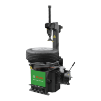
4. Mount the wheel support bracket.
652061-05_Mi
5. Put an appropriate lubricator in the mounting paste
holding device.
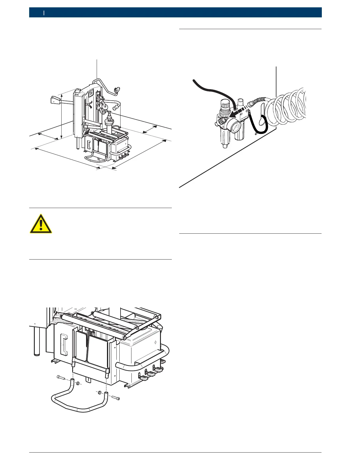
4.3 Pneumatic connection
1. Connect the TCE 4540 to the compressed air supply
unit.
652004-06_Mi
2. Adjust to a pressure between 8 and 12 bar.
Pull the red knurled screw (pressure reducing val-
ve) fi rst upwards and then twist it to adjust ope-
rating pressure.
Check pressure on the manometer.
4.4 Electrical connection
1. Check the correspondence of the mains tension and
the tension shown on the identification tag.
2. Ask a qualified electrician to mount a connection
plug for single-phase or (depending on the tension
you have ordered ) three-phase current (see the
electrical connections diagram inside the electrical
panel).
i The costs of arranging a mains protection device for
the plug are borne by the customer.
3. Protect the TCE 4540 according to specific national
rules.