Do you have a question about the Bosch TriTech+ Professional ISC-PDL1-WAC30G and is the answer not in the manual?
Covers initial steps for mounting and connecting wires to the detector.
Details IP rating, environmental class, SELV, and certifications like NF A2P.
Steps for installing optional mounting brackets like B328 and B335.
Detailed wiring instructions for connecting the detector.
Explains DIP switch settings and voltage impact on terminal functions.
Identifies spare terminals and provides a legend for terminal functions.
Details how to perform a walk test and the associated LED indications.
Explains the alarm memory feature and how it identifies units experiencing an alarm.
Illustrates short and long range coverage patterns for detection.
Differentiates between Microwave and Passive Infrared (PIR) detection technologies.
Explains how to enable or disable the anti-mask feature.
Provides steps to clear an antimask condition from the detector.
Describes the optional look-down detection zone.
Instructions for adjusting the microwave range for optimal coverage.
Details the meaning of various LED color flashes for different detector states.
Explains how to enable, activate, and disable the local walk test LED.
Describes the automatic remote self-test triggered by walk test changes.
Explains the LED indications for self-test and remote self-test failures.
Instructions on how to recall and clear trouble conditions from memory.
Summarizes LED indications for Anti-Mask, Self-Test, and Low Input Power.
Details the local/remote walk test LED and alarm memory polarity settings.
Explains the low power supervision activation when voltage falls within a specific range.
Lists compliance statements for various languages regarding Directive 1999/5/EC.
Summarizes wall tamper, system set/unset, and walk test LED status.
| Coverage Angle | 90° |
|---|---|
| Microwave Frequency | 10.525 GHz |
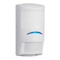
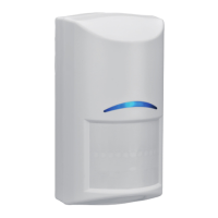
| Type | TriTech Detector |
| Technology | Passive Infrared (PIR) and Microwave |
| Power Supply | 9 V to 15 V DC |
| Operating Temperature | -30°C to +55°C |
| Mounting Height | 2.75 m |
| Alarm Relay | Form C |
| Current Consumption | 18 mA (typical), 23 mA (maximum) |
| Tamper Protection | Front and rear tamper switches |