1 695 654 761 2008-10-17| Robert Bosch GmbH
24 | WBE 5210 | Auto-diagnosis menuen
0_107.4
Page for the monitor of analog entries.
From this menu you can directly read the signal that
comes from the sensors (pick-ups and potentiometers).
This means that you can identify the cause of the de-
fect.
Here you have a summary of the functions:
Left Display
Right Display
Description
0 2050 Reading of the analog en-
try of the external pick-up
1 2050 Reading of the analog en-
try of the internal pick-up
2 2050 Reading of the analog entry of
the external enlarged pick-up
3 2050 Reading of the analog entry of
the enlarged internal pick-up
4 200 Reading of the sen-
sor of the distance
(only SBM150)
5 200 Reading of the sensor of the width
(only SBM150)
6 200 Reading of the sen-
sor of the diameter
(only SBM150)
0 - Signal of the external pick-up. 7.4.1
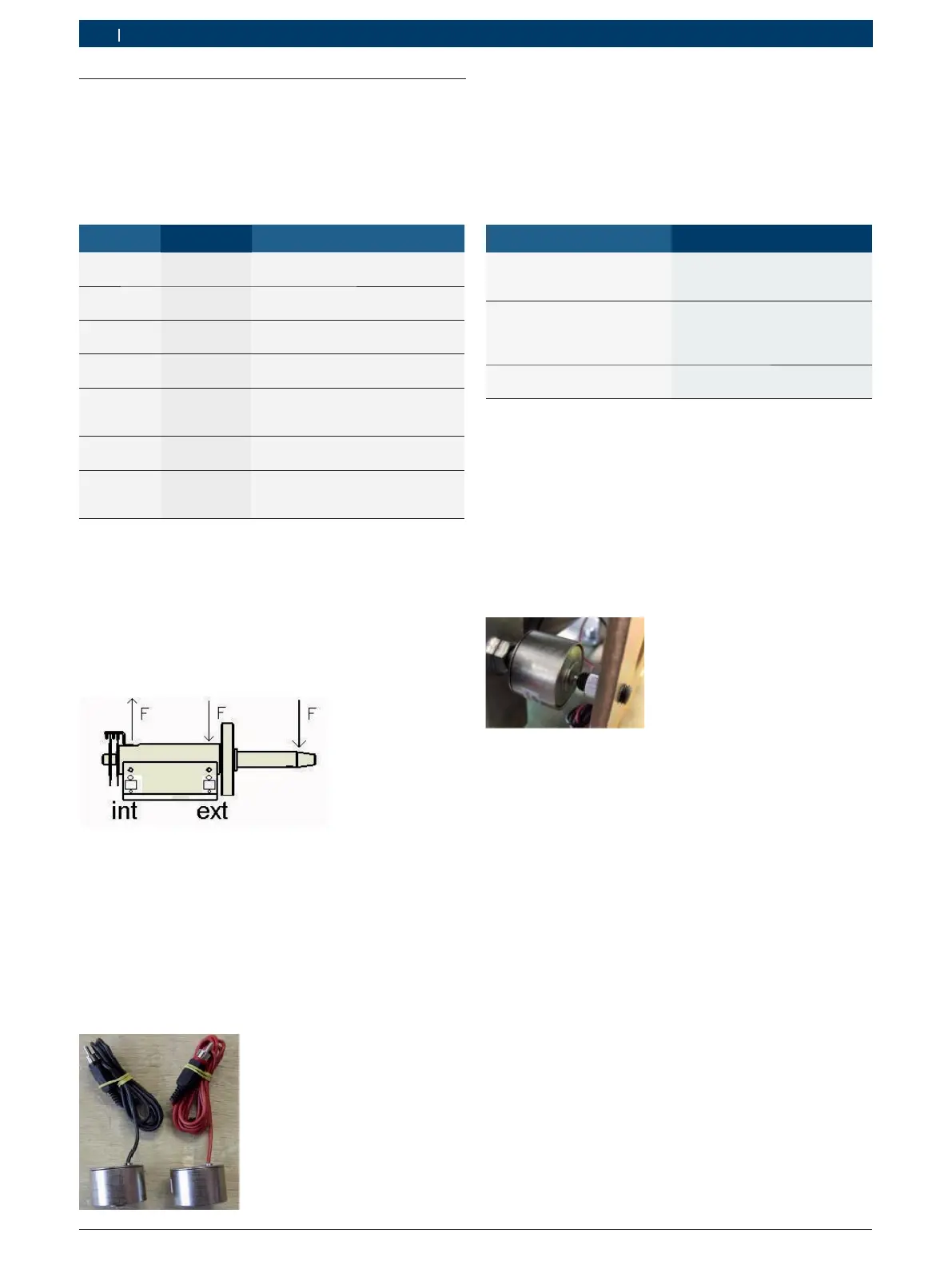
The piezoelectric sensor reads a strength variation.
During the checking phase, verify that:
the value of rest is in the middle of the reading scale;
if you push the shaft down, the value increases up to
the end of the scale;
if you lift the shaft up, the value decreases to zero.
1 - Signal of the internal pick-up.7.4.2
Now the sensor is mounted in the other position.
During the checking phase, verify that:
the value of rest is in the middle of the reading scale;
if you push the shaft down, the value decreases to
zero;
if you lift the shaft up, the value increases up to the
end of the scale.
NOTES OR THE ASSISTANCE:
The sensors (code 654432) are identical and in order to
distinguish them during the production, they mount the
red pick-up outside and the black one inside.
Here you can find some examples and possible solu-
tions:
Defect
Correction
One of the pick-ups reached
the saturation point: the
tension is 0 or 4095.
Substitute the board.
Substitute the pick-up.
You can see the difference
between the rest values: ex.
Internal 2050 (from 2000 to
2100 OK) - External 1900.
Reposition the pick-ups.
Substitute the pick-up (in
our case the external one).
The machine often
needs to be set.
Reposition the pick-ups.
Substitute both the pick-ups.
During the assistance, if you have the opportunity, we
suggest substituting the main board (chapter 9) of the
machine as it is a easier and quicker procedure than
the substitution of the pick-ups. If the problem persists,
even after the substitution of the board, mount again
the old board and substitute the sensor/s as explained
here. The only difference between the tension adjust-
ment and the substitution of the pick-up is that in the
second case you replace the sensor with a new one.
How to substitute a pick-up:
Remove the carter;
Disconnect the action-centre;
Loose the two locking screws (n° 10) that are posi-
tioned under the measure group;
Completely unscrew the special screw, which is
positioned under the pick-up (n° 8), through the use
of a 17mm key;
Remove the sensor of the pick-up;
Position the two spheres (n° 5 and n° 7) on the new
sensor. Help yourselves with some oil grease to keep
them in position;
Position the pick-up;
Screw the special key (n° 8) through the use of a
17mm key so that you will be able to rotate the sen-
sor
manually by pushing lightly;
Bring the cable of the sensor of the pick-up on the
external side of the measure group;
Tighten the cable and make a rotation at 180°
through the use of a 17mm key or apply a 6N
strength through the use of a dynamometric key.



 To Next Page