50 | Making the electrical connections
Greenstar6 720 806 992 (2015/03)
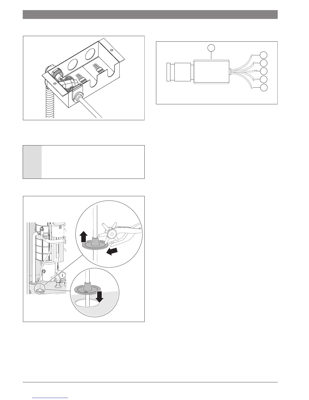
▶ Connect white plugs and insert grommet until stop.
Fig. 57 Cable connected (mains power supply)
▶ Mount junction box on the rail.
7.4 Connecting the LWCO device
▶ Punch a hole (maximum diameter 3/16" (5 mm)) through the fan
cable grommet (steps 1 – 3) and run the LWCO cable through it.
Fig. 58 Punch a hole in fan cable grommet for LWCO cable
▶ Install a 24VAC 20VA transformer near the boiler.
▶ Follow LWCO manufacturer’s instructions.
▶ Connect the lead labeled BOILER GROUND (green) to pin 2 (center,
Fig. 56 [2]) of the white plug in the boiler junction box.
▶ Connect the leads labeled 24V HOT (red) and 24V COMMON (white)
to the external 24VAC transformer.
▶ Connect the leads labeled SWITCH CONTACT (yellow) to the TB1
temperature guard ( Fig 47, page 47) on the Heatronic.
Fig. 59 Wires of a LWCO device with LWCO adapter
[1] LWCO device (Hydrolevel Safgard 1100)
[2] BOILER GROUND (green)
[3] SWITCH CONTACT (yellow)
[4] SWITCH CONTACT (yellow)
[5] 24V HOT (red)
[6] 24V COMMON (white)
NOTICE: System damage or malfunction!
▶ Ensure the air box remains air-tight when routing the
LWCO cable to the outside.
▶ Do not route the LWCO cable through the ignition
cable grommet as appliance malfunction may occur.
L
PE
N
w
hi
t
e
Mains
120V/
60
H
z
L PE N
r
e
d
Storag
e
tan
k pu
mp
L PE
N
b
lack
CH pump
for
mixed
heating
8
7
3
7 70
1
5
03
I III III II
I
6 720 641 933-39.1O
6 720 641 933-87.1O
Ø ≤ 3/16"
(~ 5 mm)
1
2
3
2
3
4
5
6
1
6 720 641 933-67.1O
 Loading...