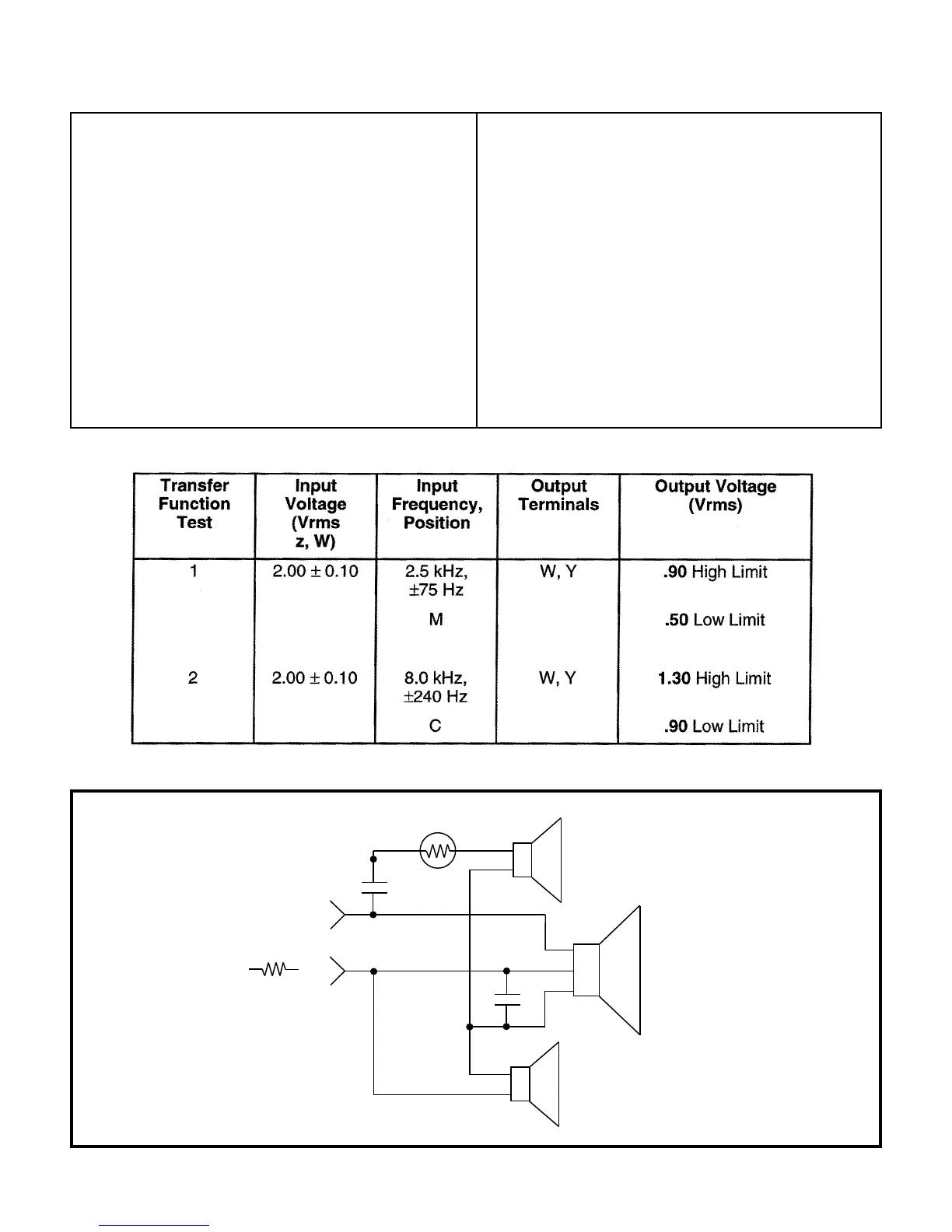
FIGURE 2
Schematic Diagram
This ensures that the woofer and speaker input
terminals are wired in phase, (see Schematic
Diagram, Figure 2).
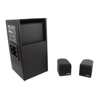
6. Tweeter Phase Test: Remove 4 screws and lift
the woofer carefully away from the speaker
cabinet in order to access the terminal cup.
Check the wiring on the terminal cup and on
both sets of tweeter terminals against the
schematic in Figure 2. This ensures that both
tweeters are wired in phase.
Crossover Measurements
Note: Due to the inaccessibility of the tweeters,
it may be necessary to remove the tweeters
from their respective endcaps. Refer to the
Disassembly Procedures on replacing
tweeters and for separating the tweeters from
the endcaps.
7. Crossover Testing: The crossover is tested by
measuring the voltage across a 10 Ω, 5 watt
resistor in series with the loudspeaker. See
Figure 2 and the following Table. If output
voltage is not within the limits shown, check
connections and component values for C1, C2,
and RT1.
6
C1
RT1
+
-
+
-
+
-
C2
YEL
2" TWEETER
8" WOOFER
3" TWEETER
BLK
YEL
RED
BLK
Z ( + )
Y ( - )
10
W
 Loading...