7
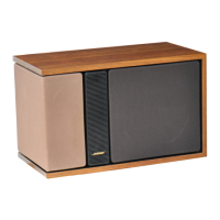
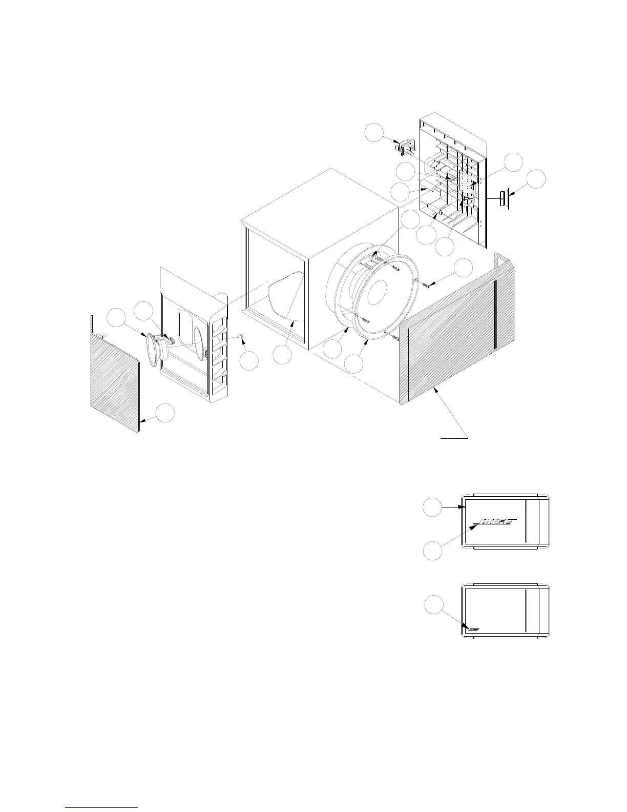
FIGURE 3: 301
®
Series IV Main Assembly Drawing
4
5
3
6
7
8
9
10
B
12
11
6
RT1
A
C1
See Detail A for Logo
Variations and Placement
2
1
2
Detail A
Logo Variations & Placement
( Left Speaker Shown )
C2
Note: Exploded view of end caps is to show
relative location of crossover components as
well as the tweeters and is not intended to
represent a serviceable part.
 Loading...