EasyManua.ls Logo

Bose Lifestyle PS 18 - User Manual

Bose Lifestyle PS 18
43 pages
To Next Page IconTo Next Page
Loading...
Lifestyle
®
28 Home Theater System
5 Double Cube Speakers
PS28 bass module
Lifestyle
®
35 Home Theater System
5 Jewel Cube
®
Speakers
PS48 bass module
Lifestyle
®
18 Home Theater System
5 Single Cube Speakers
PS18 bass module
Lifestyle
®
PS 18, 28 and 48
Digital Acoustimass
®
Powered Speakers
Service Manual
©2005 Bose Corporation
Reference Number 268795-SM
Rev 04
Electronic copy only
100V, 120V, 230V, Dual Voltage
Power PCB, Assembly - 260327-001, Bare PCB - 266459-001
AMP PCB, Assembly - 266999-0, Bare PCB - 267083-001
DSP PCB, Assembly - 267391-0, Bare PCB - 267086-001
Question and Answer IconNeed help?

Do you have a question about the Bose Lifestyle PS 18 and is the answer not in the manual?

Bose Lifestyle PS 18 Specifications

General IconGeneral
BrandBose
ModelLifestyle PS 18
CategorySpeakers
LanguageEnglish

Summary

SAFETY INFORMATION

ELECTROSTATIC DISCHARGE SENSITIVE (ESDS) DEVICE HANDLING

Precautions for repairing, replacing or transporting ESDS devices.

Specifications

Mechanical

Dimensions and weight specifications for system components.

Electrical

Electrical characteristics including amplifier power and impedance.

Lifestyle 18 Home Theater System Packaging

Figure 1. LS18 System Packaging Exploded View

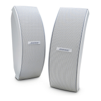
Exploded view of the LS18 system packaging components.

Lifestyle 28 Home Theater System Packaging

Figure 2. LS28 System Packaging Exploded View

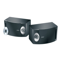
Exploded view of the LS28 system packaging components.

Lifestyle 35 Home Theater System Packaging

Figure 3. LS35 System Packaging Exploded View

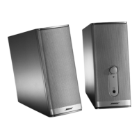
Exploded view of the LS35 system packaging components.

Lifestyle 18;28;35 Essentials Kit Part List

Figure 4. LS18, 28, 35 Essentials Kit Exploded View

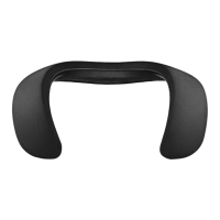
Exploded view of the essentials kit components.

Jewel Cube Part List

Figure 7. Jewel Cube Exploded View

Exploded view of the Jewel Cube speaker components.

Single and Dual Cube Speaker Part List

Figure 8. Cube Exploded View

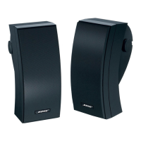
Exploded view of the single and dual cube speaker components.

PS18;28;48 Bass Module Assembly Part List

Figure 9. Bass Module Exploded View

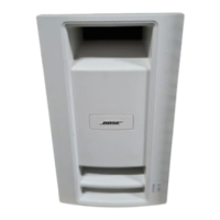
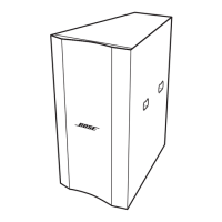
Exploded view of the bass module assembly components.

PS18;28;48 Amplifier Module Assembly Part List

Figure 10. Amplifier Module Exploded View

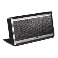
Exploded view of the amplifier module assembly components.

Placing the Bass Module into TAP Mode

Figure 12. DIP switch Up;Down orientation

Diagram showing the DIP switch positions for TAP mode.

Test Procedures

1. Sweep Test

Procedure for testing audio sweep response from 40 Hz to 300 Hz.

2. Bass Module Air Leak Test

Procedure to check for air leaks in the bass module cabinet.

3. Input to Output Gain

Procedure to measure gain from input to speaker output.

Bass Module Disassembly Procedures

1. Rear Cover Removal

Instructions for removing the rear cover of the bass module.

2. Amp Module Removal

Instructions for removing the amplifier module from the bass module.

3. Amplifier Module Cover Removal

Instructions for removing the amplifier module cover.

4. Power PCB Removal

Instructions for disconnecting and removing the power PCB.

Cube Speaker Disassembly Procedures

Double and Single Cube Disassembly

Procedure for disassembling double and single cube speakers.

Jewel Cube Disassembly

Procedure for disassembling Jewel Cube speakers.

Related product manuals