40
HI POT TEST
Hi-Pot Test:
THIS IS A MANDATORY TEST
Note: If the unit under test requires disassembly as part of the repair, it MUST be Hi-Pot tested before being
returned to the customer to ensure that there is no potential shock hazard. This test requires a Hi-Pot tester
with a ground bond attachment to perform this test.
Connections:
The Hi-Pot tester connects to the unit under test (UUT) by means of a wiring harness. The AC line cord of
the UUT plugs into the Hi-Pot tester AC adapter box. The return line connects to the output connectors on
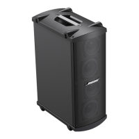
the MSA12X.
Hi-Pot Tester Settings:
2500VAC or 3540VDC, Ramp = 1second, dwell = 3 seconds, current limit = 5.0
mA. Connect the AC mains
cord to the unit under test. Plug the other end of the AC cord into the Hi-Pot tester AC adapter box. The AC
adapter box connects to the High Voltage (HV) connection on the Hi-Pot tester.
With the tester set to the above parameters, perform the test. If the unit fails, troubleshoot it and repair the
problem. Once the unit is repaired, repeat the Hi-Pot and ground bond test to ensure the unit is safe to return
to the customer.
Ground Bond Test:
Note: This test only needs to be performed if the chassis ground wire from the AC c
onnector to the inside of
the chassis of the unit has been removed or disturbed as part of the repair. If it has not, this test does not need
be performed. This test measures current handling capacity between the ground blade on the AC inlet or
mains plug and the earth bond point GND of the metal shell of the unit.
Ground Bond Tester Settings:
10A, less than 12VAC open circuit, Less than 0.1 ohms from AC earth terminal on IEC connector in chassis, to
earth bond point of the chassis. Test duration = 3 seconds. Connect the AC mains cord to the MSA12X under
test. Plug the other end of the AC cord into the ground bond test box. With the tester set to the above param-
eters, perform the test. If the unit fails, remove the chassis and repair the problem. Once the unit is repaired,
repeat the Hi-Pot and ground bond tests to ensure the unit is safe to return to the customer.
Figure 35 Figure 36
Figure 37
 Loading...
