Do you have a question about the Bose Powered Acoustimass 30 and is the answer not in the manual?
Precautions for handling ESDS devices during repair, replacement, or transport.
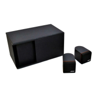
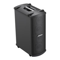
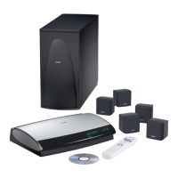
Introduction to the AM-30P system and its main features.
Describes the connection to the CD-20 and the overall audio signal path.
Details the audio signal processing from input to amplifier output.
Explains how surround channel information is decoded from stereo inputs.
Describes the role of the microcontroller in system control and protection.
Details the AC power input and DC voltage generation.
In-depth explanation of the system's electronic circuits.
Specifics of the power supply circuit operation and components.
Detailed explanation of audio signal processing stages like EQ and volume control.
Explains the circuit for detecting surround sound phase information.
Describes the gain control mechanism within the surround decoder.
Explains how audio channels are combined and routed.
Details the active filter equalization for satellite speakers.
Explains the equalization stages for the bass channel.
Describes the Class-G bass amplifier operation and power output.
Details the Class-G amplifier design for satellite speakers.
Explains the system's compressor function to prevent clipping.
Describes various protection circuits and their interaction with the microcontroller.
Steps to remove the bass module cover.
Steps to replace the bass module cover.
Steps to remove the main PCB from the bass module.
Steps to replace the main PCB in the bass module.
Steps to remove the amplifier PCB from the bass module.
Steps to replace the amplifier PCB in the bass module.
Steps to remove the power transformer from the bass module.
Steps to replace the power transformer in the bass module.
Steps to remove the woofer from the bass module.
Steps to replace the woofer in the bass module.
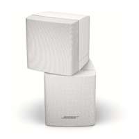
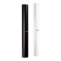
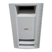
Steps to remove the grille assembly from the satellite cube.
Steps to replace the grille assembly on the satellite cube.
Steps to remove the twiddler from the satellite cube.
Steps to replace the twiddler on the satellite cube.
Configuration of test modes for troubleshooting without a CD-20.
Procedure to test the system's signal gain across channels.
Tests the gain of the bass channel output.
Tests the left channel output for decoder performance.
Tests the right channel output for decoder performance.
Tests the center channel output for decoder performance.
Tests the surround channel output for decoder performance.
Tests the frequency response of the bass channel.
Tests the frequency response for left and right channels.
Tests the frequency response for the center channel.
Tests the frequency response for the surround channel.
Tests dynamic equalization behavior based on volume level.
Tests the mute function of the volume control ICs.
Measures small signal distortion levels for amplifier output.
Measures large signal distortion levels for amplifier output.
Tests the operation of the audio compressor circuit.
Measures DC offset voltage at amplifier outputs.
Measures noise levels across different channels.
Tests the bass module for unwanted sounds during frequency sweep.
Checks for air leaks in the bass module cabinet.
Tests the functionality and smoothness of tone controls.
Information on identifying different PCB versions for AM-P modules.