2
Contents
Safety Information............................................................................................................................ 3
Electrostatic Discharge Sensitive (ESDS) Device Handling ........................................................ 4
Specifications ................................................................................................................................... 5
Theory of Operation .................................................................................................................... 6-18
Figure 1. Center Channel Frequency Response............................................................................ 10
Figure 2. Surround Channel Frequency Response........................................................................ 11
Figure 3. Bass and Left/Right Channel Frequency Response ....................................................... 11
Figure 4. Dynamic Equalizer Frequency Response....................................................................... 11
Figure 5. Voltage at Collector of Q381 (Bass Amplifier) ................................................................. 16
Figure 6. Treble Control Frequency Response .............................................................................. 16
Figure 7. Simplified Block Diagram of Shared 2 Channel Class-G Amplifier ................................. 19
Figure 8. PCB Block Diagram ........................................................................................................ 20
Figure 9. Surround Decoder Block Diagram .................................................................................. 21
Disassembly/Assembly Procedures ....................................................................................... 22-28
Figure 10. Screw Location ............................................................................................................. 22
Figure 11. Cover Latch Rotated In ................................................................................................. 22
Figure 12. Cover Latch Rotated Out .............................................................................................. 22
Figure 13. Base-Plate Tabs ............................................................................................................ 22
Figure 14. Module Enclosure Disassembly .................................................................................... 24
Figure 15. Cover Assembly ............................................................................................................ 24
Figure 16. Module Assembly Exploded View ................................................................................. 25
Figure 17. Heatsink/Amplifier PCB Subassembly .......................................................................... 25
Figure 18. Woofer Harness Hookup............................................................................................... 27
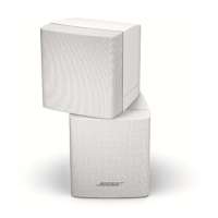
Figure 19. AM-30P Satellite Cube Array ........................................................................................ 28
Test Set-Up Parameters ................................................................................................................. 29
Test Procedures ........................................................................................................................ 30-33
Part List Notes................................................................................................................................ 34
PCB Identification .......................................................................................................................... 34
Main Part List.................................................................................................................................. 35
Figure 20. Bass Module Exploded View ........................................................................................ 36
Figure 21. Module Assembly Exploded View ................................................................................. 36
Electrical Part List ..................................................................................................................... 37-42
Satellite Part List ............................................................................................................................ 43
Figure 22. Satellite Exploded View ................................................................................................ 43
Packing Part List ............................................................................................................................ 44
Figure 23. Packing ......................................................................................................................... 45
Integrated Circuits .................................................................................................................... 46-48
 Loading...