1
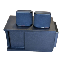
CAUTION: THE ACOUSTIMASS
®
-3 POWERED SPEAKER SYSTEM
CONTAINS NO USER-SERVICEABLE PARTS. TO PREVENT
WARRANTY INFRACTIONS, REFER SERVICING TO WARRANTY
SERVICE STATIONS OR FACTORY SERVICE.
PROPRIETARY INFORMATION
THIS DOCUMENT CONTAINS PROPRIETARY INFORMATION OF
BOSE
®
CORPORATION WHICH IS BEING FURNISHED ONLY FOR
THE PURPOSE OF SERVICING THE IDENTIFIED BOSE PRODUCT
BY AN AUTHORIZED BOSE SERVICE CENTER OR OWNER OF THE
BOSE PRODUCT, AND SHALL NOT BE REPRODUCED OR USED
FOR ANY OTHER PURPOSE.
Table of Contents
SAFETY INFORMATION...................................................................................................... 2
ELECTROSTATIC DISCHARGE SENSITIVE (ESDS) DEVICE HANDLING....................... 3
SPECIFICATIONS ................................................................................................................ 4
Figure 1. Bass Channel Frequency Response Curve ................................................ 5
Figure 2. Left/Right Channel Frequency Response Curve ........................................ 5
Figure 3. AM-3P II Amplifier PCB Assembly Block Diagram...................................... 6
Figure 4. AM-3P II Equalizer PCB Assembly Block Diagram ..................................... 6
AM-3P II THEORY OF OPERATION .................................................................................... 7
AM-3P II DISASSEMBLY/ ASSEMBLY PROCEDURES ................................................... 13
AM-3P II TEST PROCEDURES ......................................................................................... 18
Figure 5. 120/240V Transformer Schematic .............................................................. 22
Integrated Circuit Diagrams ............................................................................................. 23
PART LISTS AND EXPLODED VIEWS ............................................................................. 26
AM-3P II Bass Module Part List .................................................................................. 27
AM-3P II Satellite Part List .......................................................................................... 28
Figure 6. AM-3P II Bass Module Exploded View ....................................................... 29
Figure 7. Woofer Location in Module......................................................................... 30
Figure 8. Satellite Exploded View............................................................................... 30
AM-3P II Packaging List .............................................................................................. 31
Figure 9. AM-3P II Packaging Exploded View ........................................................... 33
AM-3P II Main PCB Assembly Part List...................................................................... 34
AM-3P II Amplifier PCB Assembly Part List .............................................................. 39
SCHEMATICS AND PCB LAYOUTS.................................................................................. 42
Note: This service manual has been updated with information from service manual supplement
175032-S2. This supplement affects part number for R146 and R246 as used on the amplifier PCB.
Refer to 175032-S2 for more information.




 Loading...