7
AM-3P II THEORY OF OPERATION
NOTE: The following discussion references the AM-3P II/Multimedia Main and Amplifier
PCB schematics, and block diagrams. The block diagrams, Figures 3 and 4, can be found
on page 6 and the schematics are located in the back of this service manual.
GENERAL
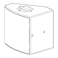
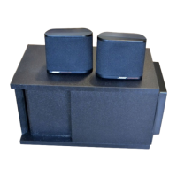
The AM-3P II powered Acoustimass
®
loudspeaker system is manufactured in two variations:
Home Audio and Multimedia. Both variations can be used with the Bose
®
Lifestyle
®
Music
System or other sources that have line-level outputs. The multimedia variation was designed
specifically for computer sound amplification. The basic differences of the multimedia are as
follows:
• 10dB higher gain to accommodate the lower output level of computer sound cards.
• Higher input impedance for compatibility with most industry standard audio equipment.
• RCA input jacks allow mixing of two separate stereo signals (Source 1 and Source 2 inputs).
The AM-3P II is based acoustically on the AM-3P Series I Acoustimass
®
powered loud-
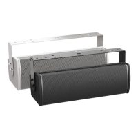
speaker system. The distinguishing difference between Series I and Series II is the change
to a new satellite enclosure (AM-4), and equalizer PCB assembly designed to compensate
for the acoustic differences of this new enclosure. Listed below are some of the features of
the AM-3P II.
• Automatic turn-on/turn-off mute of the amplifier output stage
• Automatic (BOSE
®
patented) dynamic equalization
• Bi-amplification for better power distribution to speakers
• Active equalization for smoother frequency response
• Amplifier short-circuit and DC offset fault protection
• Local volume/sensitivity control
• Bass/treble room compensation controls
• Differential input stage (to reject hum)
• Dynamic compressor to prevent amplifier output overload distortion
BLOCK DIAGRAM DESCRIPTION
NOTE: In the discussion of L/R (left/right) channels, only the right channel is discussed. The
left channel operation is identical.
1. Power Supply
A single, universal, 115/230V EI core power transformer is used to power the system. It has
been specially designed for minimum magnetic flux leakage and stand-by power consumption.
The transformer primary remains energized (always on) except when the power switch is in the
off position.