EasyManua.ls Logo

Boss RDD-20 - RDD-20;10 Adjustment Procedures; Compressor Adjustment; Expander Adjustment; Clock Frequency Calibration

Boss RDD-20
4 pages
Print Icon
To Previous Page IconTo Previous Page
Loading...
RDD-20/10
SEP.
1986
AD
J USTM
ENT
(RDD-20/10)
H8
Set the
front
panel switches and controls
as follows
:
;Hr
77
^
>
$
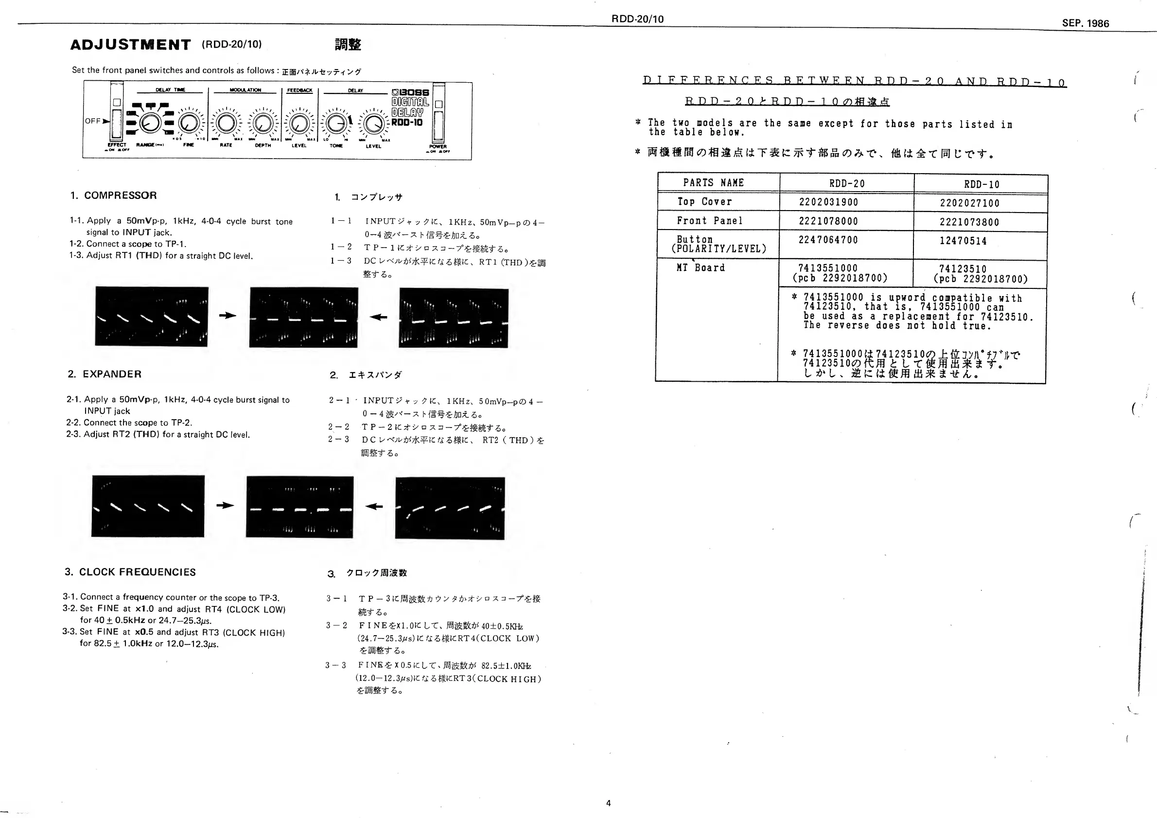
1.
COMPRESSOR
1.
3
>7"U7t
1-1.
Apply
a 50mVp-p, 1kHz,
4-0-4
cycle
burst
tone
signal
to INPUT
jack.
1-2.
Connect
a
scope to TP-
1 .
1-3.
Adjust
RT1 (THD) for
a straight
DC level.
1-1
I NPUT
i/
t
;
lKHz,
50mVp-p6D4-
0—4
^
s
'—
7,
h
60
1-2
TP-llCt->o7
3-7
0
^t-50
1-3
DC
RT
1
(THD
)£fgj
2. EXPANDER
2.
2-1.
Apply
a 50mVp-p, 1kHz,
4-0-4
cycle burst signal
to
INPUT jack
2-2.
Connect the
scope to
TP-2.
2-3.
Adjust
RT2
(THD) for
a
straight DC level.
2-1
•
INPUTS
+
-j
^
{C
%
lKHz,
5
OmVp—
pCQ
4
—
0-4
*
h
(f
5
0
2
-2
TP
-2 ICd-'>a
^
2-3
DC
RT2
(
THD
)
£
issiiT
-S o
%
V
'V
\
3. CLOCK
FREQUENCIES
3-1.
Connect
a frequency
counter
or
the
scope
to TP-3.
3-2.
Set FINE
at xl.O and
adjust
RT4
(CLOCK
LOW)
for
40
±
0.5kHz
or
24.7-25.3ps.
3-3.
Set FINE
at
xO.5 and
adjust
RT3
(CLOCK
HIGH)
for
82.5
±
1
.0kHz or
1 2.0-1
2.3/ts.
3.
3-1
T P
-
7
-5>o
3-2
FINE^-XI.OICLT,
40±0.5KHz
(24.7—
25.3/^s)
1C
^
-S^ICRT4(CLOCK
LOW)
;
&113llE"T
dE>
o
3-3 FINE£
X0.5ICLT,
82.5±1.0KHz
(12.0—
12.3/^s)IC
££ -S
JiiCRT 3(
CLOCK
HIGH)
'SrtSiSIlF
&
o
D I F F F.-R.E N CES BETWEEN R
n n
-
2
0
AND R Tt n
-
i n
Rnn-2o>Rpn-i
n yiiaai
*
The
t«o models
are
the same
except
for those
parts
listed
ia
the
table
below.
*
c-rt.
PARTS
NAME
RDD-20
RDD-10
Top
Cover
2202031900
2202027100
Front Panel
2221078000
2221073800
Button
(POLARITY/LEVEL)
2247064700
12470514
MT
Board
7413551000
(pcb
2292018700)
74123510
(pcb
2292018700)
*
7413551000
is upword
compatible
with
74123510, that
is,
7413551000
can
be
used
as
a
replacement
for
74123510.
The
reverse
does
not
hold
true.
*
74
1355
1000 (±
74 12351
0<5D±&;i»r?
74123510^0
ftffl t L X
&
.
L&ls
ft*
4