EasyManua.ls Logo

Boss Roland GT-8 User Manual

Boss Roland GT-8
31 pages
To Next Page IconTo Next Page
Page #1 background imageLoading...
Page #1 background image
SERVICE NOTES
Issued by RJA
Copyright © 2004 ROLAND CORPORATION
All rights reserved. No part of this publication may be reproduced in any form without the written permission
of ROLAND CORPORATION.
Printed in Japan (0500) (AS)17058309E0
Dec.2004
GT-8
TABLE OF CONTENTS
CAUTIONARY NOTES........................................................ 2
SPECIFICATIONS................................................................. 2
LOCATION OF CONTROLS............................................... 4
LOCATION OF CONTROLS PARTS LIST ....................... 6
EXPLODED VIEW ................................................................ 8
EXPLODED VIEW PARTS LIST ....................................... 10
WIRING DIAGRAM........................................................... 11
WIRING DIAGRAM PARTS LIST.................................... 11
PARTS LIST.......................................................................... 12
CHECKING THE VERSION NUMBER........................... 17
USERS DATA SAVE AND LOAD.................................... 17
FACTORY RESET INSTRUCTIONS .................................18
SYSTEM SOFTWARE UPDATING INSTRUCTIONS....19
TEST MODE.......................................................................... 19
BLOCK DIAGRAM .............................................................24
CIRCUIT BOARD (MAIN SHEET) ...................................26
CIRCUIT DIAGRAM (MAIN SHEET 1/3) (Power) .......30
CIRCUIT DIAGRAM (MAIN SHEET 2/3) (Jack) ...........32
CIRCUIT DIAGRAM (MAIN SHEET 2/3) (Digital) ......34
CIRCUIT BOARD (SW SHEET).........................................36
CIRCUIT DIAGRAM (SW SHEET) ...................................38
ERROR MESSAGES............................................................. 40
Question and Answer IconNeed help?

Do you have a question about the Boss Roland GT-8 and is the answer not in the manual?

Boss Roland GT-8 Specifications

General IconGeneral
Sampling Rate44.1 kHz
DA Conversion24-bit
Nominal Input Level-10 dBu
Nominal Output Level-10 dBu
TypeGuitar Effects Processor
EffectsDelay, Reverb
Bit Depth24-bit
Input1/4" phone type
Output1/4" phone type (L/MONO, R)
Power SupplyAC Adaptor (included)
AD Conversion24-bit
Input Impedance1 MΩ
Dynamic Range100 dB
DisplayBacklit LCD
ConnectorsMIDI (IN, OUT)
ConnectivityMIDI (IN, OUT)
Power Supply VoltageDC 9V

Summary

CAUTIONARY NOTES

User Data Status and Notes

Details user data handling and notes on parts/circuit boards.

SPECIFICATIONS

GT-8 Technical Specifications

Comprehensive specs including AD/DA, sampling, I/O, and dynamic range.

Front Panel Controls Overview

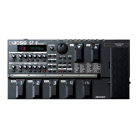
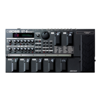
Lists and describes the GT-8's front panel controls.

Front Panel Controls (Continued)

Connectors, Power, and Dimensions

Details connectors, power supply, current, dimensions, and weight.

Accessories and Options

Lists included accessories and optional items for the GT-8.

LOCATION OF CONTROLS

Front and Rear Panel Layouts

Diagrams illustrating the placement of all controls and connectors.

LOCATION OF CONTROLS PARTS LIST

Parts List Details

Table of parts for control locations, including part codes and quantities.

EXPLODED VIEW PARTS LIST

Exploded View Parts and Screws

Lists parts and screws identified in the exploded view.

WIRING DIAGRAM

Wiring Diagram and Parts List

Shows internal wiring connections and lists associated parts.

PARTS LIST

Casing, Knobs, Switches, and Jacks

Lists parts for casing, controls, switches, and connectors.

PWB Assemblies, ICs, and Display

Lists main board assemblies, integrated circuits, and display components.

CHECKING THE VERSION NUMBER

Version Number Check Procedure

Steps to display the GT-8's software version number.

USERS DATA SAVE AND LOAD

MIDI Data Transmission

How to transmit settings via MIDI (Bulk Dump).

SYSTEM SOFTWARE UPDATING INSTRUCTIONS

Required Equipment and Procedure

Lists necessary items and steps for updating system software.

TEST MODE

Test Categories and Entering Test Mode

Lists available tests and how to access Test Mode.

Quitting Test Mode and VR Checks

Procedures for exiting Test Mode and checking VR controls.

EXP Pedal and Switch Checks

Steps to verify the expression pedal and button functionality.

Battery, MIDI, and AMP CTRL Tests

Tests for battery status, MIDI I/O, and AMP Control.

Output D/A and External Loop Tests

Tests for digital-to-analog output and external effects loop.

Input A/D, DSP, and Noise Tests

Tests for analog-to-digital input, DSP, and noise levels.

Calibrate EXP Pedal

Procedure to calibrate the expression pedal settings.

BLOCK DIAGRAM

Main Sheet Block Diagram

Schematic illustrating the main components and their interconnections.

CIRCUIT BOARD (MAIN SHEET)

Main Board Component Layout

Diagram showing the placement of components on the main circuit board.

CIRCUIT DIAGRAM (MAIN SHEET 1/3) (Power)

Power Supply Circuitry

Detailed schematic of the power supply section of the main board.

CIRCUIT DIAGRAM (MAIN SHEET 2/3) (Jack)

Jack and Analog Circuitry

Schematic detailing the analog signal path and jacks.

CIRCUIT DIAGRAM (MAIN SHEET 2/3) (Digital)

Digital Signal Processing and Interfaces

Schematic illustrating digital signal paths and interfaces.

CIRCUIT BOARD (SW SHEET)

Switch Board Component Layouts

Diagrams showing component placement on various switch boards.

CIRCUIT DIAGRAM (SW SHEET)

Switch Board Wiring Schematics

Detailed wiring diagrams for the switch boards.

ERROR MESSAGES

Battery and MIDI Errors

Explains "Battery Low" and "MIDI Off Line" error messages.

Value Lock and Buffer Errors

Explains "VALUE Locked" and "MIDI Buffer Full" error messages.

No Battery Error

Explains the "No Battery!!" error message.

Related product manuals