7
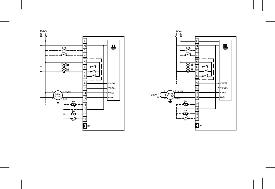
Fig. 8: Schema di collegamento per pilotaggio di due attuatori on/off
a 230V~ per impianto a 4 tubi e pilotaggio proporzionale del
ventilatore.
Wiring diagram for 2 on/off 230V~ actuators in 4 pipes system
and proportional fan drive.
Fig. 9: Schema di collegamento per pilotaggio di due attuatori on/off
a 24V~ per impianto a 4 tubi e pilotaggio proporzionale del
ventilatore.
Wiring diagram for 2 on/off 24V~ actuators in 4 pipes system
and proportional fan drive.
P01: 1
P05: 0 (1)
P06: 2 (3)
P07: 2 (3)
P01: 1
P05: 0 (1)
P06: 2 (3)
P07: 2 (3)