8
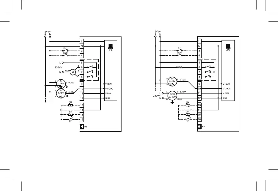
Fig. 10: Schema di collegamento per pilotaggio di due attuatori 0..10V
a 24V~ per impianto a 4 tubi e pilotaggio di un motore a tre
velocità a 230V.
Wiring diagram for two 0..10V 24V~ actuators in a 4 pipes
system and one 230V three speeds motor.
Fig. 11: Schema di collegamento per pilotaggio di un attuatore 0..10V a
24V~ per impianto con resistenza di integrazione e pilotaggio
proporzionale del ventilatore.
Wiring diagram for a 0..10V 24V~ actuator for an electric he-
ater integration system and driving of a proportional fan motor.
P01: 1
P05: 2
P06: 0 (1)
P07: 0 (1)
P01: 2 (3)
P05: 0 (1)
P06: 2
P07: 0 (1)