9
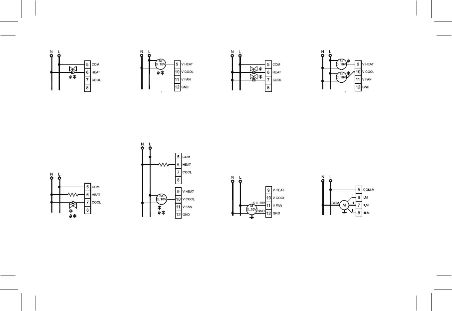
Fig. 12a.
Sistema a 2 tubi con una valvola
ON/OFF.
2-pipes system with ON/OFF valve.
Fig. 12b.
Sistema a 2 tubi con un
servocomando 0..10V.
2-pipes system with 0..10V
servocontrol.
Fig. 12c.
Sistema a 4 tubi con due valvole
ON/OFF.
4-pipes system with two ON/OFF
valves.
Fig. 12d.
Sistema a 4 tubi con due servoco-
mandi 0..10V.
4-pipes system with two 0..10V
servocontrols.
Fig. 12e.
Sistema con resistenza di integra-
zione e con una valvola ON/OFF.
Electric heater system with a ON/
OFF valve.
Fig. 12f.
Sistema con resistenza di inte-
grazione e con un servocomando
0..10V.
Electric heater system with a
0..10V servocontrol.
Fig. 13a.
Collegamento di un ventilatore pro-
porzionale con motore elettronico
(EC motor) con ingresso 0..10V.
Connection of a proportional fan
with an EC motor with 0..10V input.
Fig. 13b.
Collegamento di un ventilatore con
motore a tre velocità.
Connection of a fan with a three
speeds motor.
P01: 0
P06: 2(3)
P01: 0
P06: 0(1)
P01: 1
P06: 2(3)
P07: 2(3)
P01: 1
P06: 0(1)
P07: 0(1)
P01: 2(3)
P06: 2(3)
P07: 2(3)
P01: 2(3)
P06: 2(3)
P07: 0(1)
P05: 0(1) P05: 2