elapsed, or on completion of the
electrical door lock function.
3 - Call note.
The unit is equipped with two diffe-
rential call tone generators.
The first generator (terminal 8) is
activated each time a call is made at
the entry panel which simultaneously
causes the system activation timers
to switch on.
The second generator (terminal 8A
and jumper SW in figure 1 energi-
sed) activates without switching on
the system. This means that the
second generator may be used as a
landing call signal.
When jumper SW is de-energised,
the activation of the second genera-
tor causes the system to switch on,
and permits, if required, the identifi-
cation of two call sources (2 entry
panels).
The outputs of the two call genera-
tors can simultaneously control a
maximum of 3 internal units.
4 - Door lock release (12V 1A)
The supply voltage to the electrical
door lock is limited to approximately
1 to 15 secs. (adjusted using the
potentiometer in figure 1) also
with continuous activation of the
door lock release button on the inter-
nal unit.
If the door lock release is activated
by an auxiliary button (connected to
terminal 23), the electrical door lock
is energised for the duration of acti-
vation of the said button.
5 - Conversation privacy.
The unit powers audio and video
conversation privacy when the moni-
tors and handsets (200 and EXEDRA
200 series) are installed in the same
system. The handsets must be
equipped with SC/200 unit.
The use of C/200 handset, in
systems without conversation pri-
vacy, requires the installation of
EKC/200 capacitor.
6 - Stair light control.
The stair light function may be acti-
vated using the monitor (when swit-
ched on) using relay VLS/101.
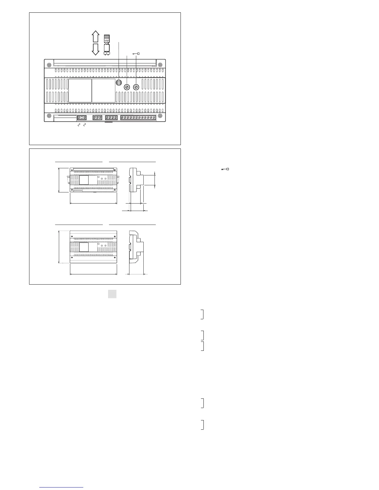
Function of each terminal, figure 1
Terminal block A
~
mains
~
Terminal block B
5 - 17.5V supply voltage
6 + to entry panel
5 - 12V supply voltage audio
21 + entry system accessories
8 call common 1
8A call common 2
22 stair light actuator output
(VLS/101)
11 audio to monitor
12 audio to entry panel
23 auxiliary door lock release but-
ton
14 entry panel activation
13 + 12V supply voltage
16 - to electrical door lock
Terminal block C
5 - 17.5V supply voltage
6 + to monitor and accessories
8 audio to monitor
9 audio to entry panel
Terminal block D
(coaxial cable connection)
3 video signal
4 video signal shield
7 call no. 1
Terminal block D
(twisted pair connection)
3 positive video signal
4 negative video signal
7 call no. 1
Technical features
• Supply voltage: 230V 50/60 Hz.
Self-resetting electric safety switch.
• Rated power: 60VA.
• Output voltages:
17.5V DC stabilised (0.9A for con-
tinuous service and 0.6A for inter-
mittent service) for monitor, entry
panel and accessories.
12V DC stabilised (400mA for con-
tinuous service)
12V DC (0.5A for intermittent servi-
ce) for electrical door lock.
• Two differential call note genera-
tors, controlling up to 3 internal
units.
• Installation activation time 30 secs.
If the handset is lifted during this
interval, the activation time is
extended by 30 to a maximum of
90 secs. (adjustable).
• Electrical door lock activation time
with time interval adjustment of 1
to 15 secs. Compatible with both
direct and alternate current-opera-
ted electrical door lock (12V DC,
AC, 1A).
• Stair light actuator output: type
VLS/101.
• Working temperature range: from
0 °C to +35 °C.
• Dimensions: 12 DIN units, low pro-
file module, figure 2.
The unit can be installed without
terminal covers, in boxes fitted
with DIN guide (EN 50022).
See figure 2A for overall dimen-
sions.
Alternatively, it can be wall-moun-
ted using the DIN guide provided,
and applying the terminal cover.
See figure 2B for overall dimen-
sions.
NOTE. The tunit is protected against
overloads and short-cicuits by a self-
resetting thermal switch, inserted on
the primary of the power supply tran-
sformer.
Once the switch trips, operation is
resumed automatically once the tem-
perature of the transformer drops
back below 85 °C.
Make sure the cause of the switch
tripping is eliminated.
VA/200
 Loading...