entry panels’ standard program-
ming is no longer accessible.
To restore default conditions, plea-
se refer to the related chapter.
6 - RESTORING
DEFAULT CONDITIONS
6.1 - Enter receiver programming
mode;
t
he LED flashes.
6.2 - Press the SERVICE button for at
least 15 s;
the LED goes off.
7 - SELFTEST
This facility can be used to run checks
on the system installed, checking
audio and video channels for correct
connections, and making sure LON
devices (entry panels, porter switch-
boards etc.) are working properly.
7.1 - To enter selftest mode, press the
SERVICE button for about 1 s twice in
a row (maximum 3 s between 1st and
2nd time it is pressed).
The LED remains lit for an extended
period and there is a short pause to tell
you that the operation has been perfor-
med.
7.2 - Press the SERVICE button
q
uickly to exit selftest mode.
The LED goes off.
Contact BPT’s Technical Support for
information on using this facility.
FUNCTION OF YELLOW LED
- The LED flashes regularly: receiver
pr
ogramming mode on.
- LED on with short interruptions:
selftest mode on.
- LED on: entry panel programming on
or malfunctioning.
- LED of
f:
normal operation.
MALFUNCTIONING
DUE TO INCORRECT
PROGRAMMING
1 - Picture distorted or with poor
contrast:
- entry panels not programmed;
- video twisted pair polarity inverted;
- HAV/200 jumper position incorrect (T
position incorrect).
2 -
Audio problems (whistling, volu-
me low):
- entry panels not programmed;
- one of wires in audio twisted pair has
not been connected;
- entry panel volume control needs
adjusting.
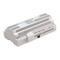
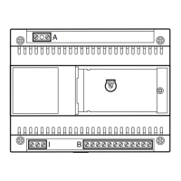
Function of each terminal, figur
e 1
T
erminal block A
L
mains
N
T
erminal block B
L LON data line
+ 18 V DC; power supply
– entry panel
A audio from entry panel
Terminal block C
B
audio entry system line
18V DC 0.2A
+ 18 V DC power supply
– monitors centralized
SW2 jumper operation (fig.1)
This is usually inserted to allow an
incr
ease in X2 line data r
eceiver sensi-
bility
.
RJ45 socket (fig. 1)
Used for connection to programming
device (IPC/300LR or MPP/300LR).
3
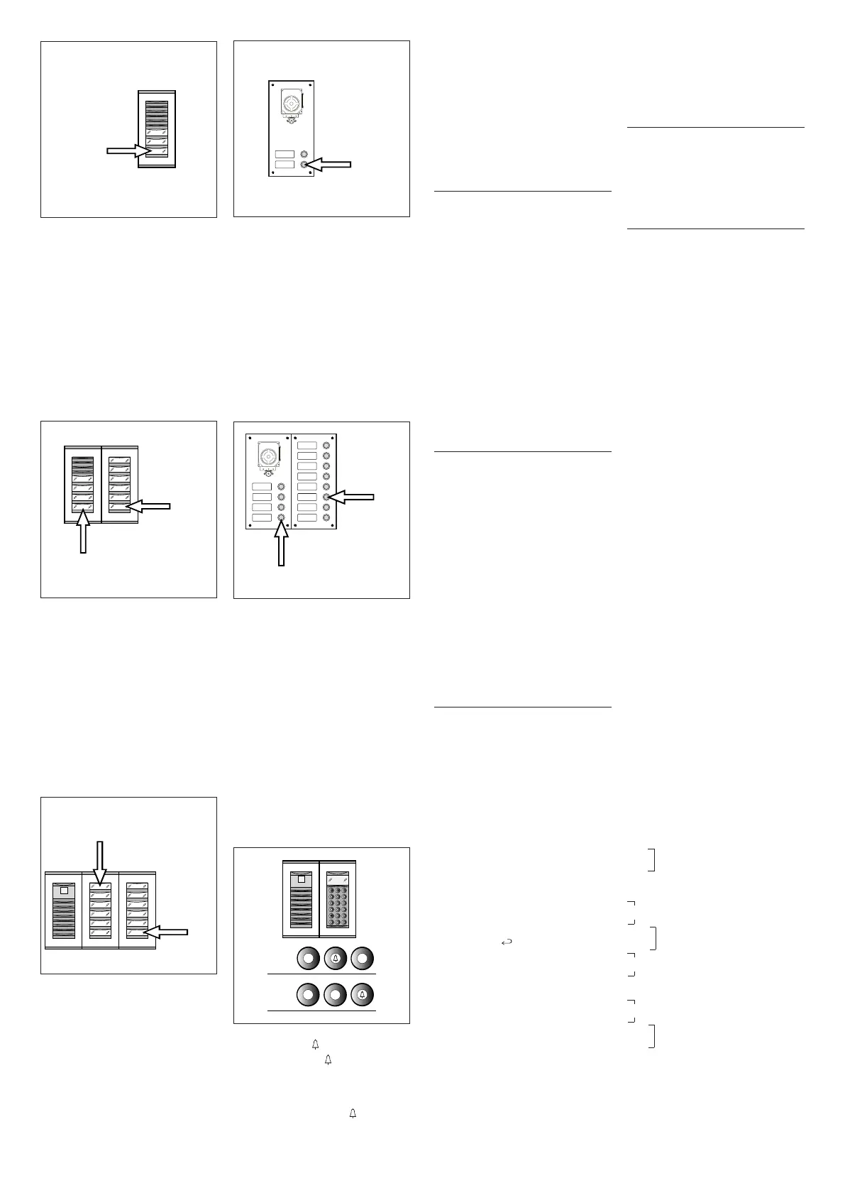
1 - Press call button n.4 (position 1B)
to set the number of buttons used (4)
on the audio/video panel.
Wait for audible confirmation (*).
2 - Then press call button n.10 (posi-
tion 2B) to set the total number of user
calls in the block (10).
Wait for audible confirmation (*).
EXAMPLE 3 -
X2 block featuring
T
ar
gha entry panel with camera with
12 calls and additional pushbutton
panels (fig. 7).
1 -
Press call button n.1 (position 1C)
to set the number of buttons used (0)
on the audio/video panel.
Wait for audible confirmation (*).
2 - Then press call button n.12 (posi-
tion 2C) to set the total number of user
calls in the block (12).
Wait for audible confirmation (*).
EXAMPLE 4 - X2 block featuring
entry panel with AZ/304 or AZV/304
with 2 calls, with no additional push-
button panels (fig. 8).
1 - Press call button n.2 (position 1D)
to set the number of buttons used (2)
on the audio/video panel.
Wait for audible confirmation (*).
2 - Press the same button again to set
the total number of user calls in the
block (2).
Wait for audible confirmation (*).
EXAMPLE 5 - X2 block featuring
entry panel with AZ/304 or AZV/304
with 10 calls and additional pushbut-
ton panels using module VZS/308C
(
fig. 9).
1 -
Press call button n.4 (position 1E)
to set the number of buttons used (4)
on the audio/video panel.
Wait for audible confirmation (*).
2 - Then press call button n.10 (posi-
tion 2E) to set the total number of user
calls used (10).
Wait for audible confirmation (*).
W
ARNING. If there is a porter swit-
chboar
d in the system, the first
button is allocated as the porter
call button.
EXAMPLE 6 -
X2 block featuring
digital T
argha entry panel with came-
ra with 20 calls (fig. 10).
5
1 - Press 4 and (if using the porter
call P, press 3 and ).
W
ait for audible confirmation (*).
2 - Pr
ess C to delete the number
displayed.
3 - Enter 20 and press to set the
total number of user calls in the block
(20).
Wait for audible confirmation (*).
(*) Type of audible confirmation
Audible confirmation consists in an
audible call signal and a double audible
signal with the solenoid door lock
r
elease command being activated.
3 - EXITING PROGRAMMING
AND AUTOMATIC
PROGRAMMING
O
F IPD/300LR AND
IOD/303LR UNITS,
WHERE APPLICABLE
If an IPD/300LR porter switchboard
or IOD/300LR accessories are instal-
led in the system, they will be detec-
ted automatically when you exit pro-
gramming (whether programming
receivers or entry panels).
In installations with no system 300 or
X
2 entry panels, you will need to
enter and exit programming mode to
program an IPD/300LR unit.
Every time you exit programming, the
yellow LED lights for approx. 1 s to
i
ndicate that the automatic program-
ming operation has been completed.
The LED goes off to tell you that you
have exited programming.
4 - PROGRAMMING
SLAVE X2
ENTRY PANELS
This procedure must be performed
once you have programmed the units
described in point 2.
4.1 - Start with the block’s Master
e
ntry panel
.
4.2 - Remove the SW1 jumper from
the X2 block Master entry panel (the
one connected to the XA/300LR
power supplier).
4.3 - Wait for the audible signal confir-
ming the operation.
The number of notes equals the total
number of X2 entry panels connected
to the block (you may have to wait 3 to
15 s for audible confirmation).
4.4 - Refit jumper SW1.
5 - CHANGING
THE DEFAULT USER
PROGRAMMING DEVICE
The device for programming the recei-
vers can be chosen before entering
programming mode with the receiver.
WARNING. The user programming
device can only be changed once
you have programmed the entry
panels (chapter 2) and/or
IPD/300LR switchboard (chapter 3).
Pr
oceed as follows:
5.1 -
Enter receiver programming
mode.
- From the system 300 entry panel you
plan to use for programming, make a
call to any of the receivers (a note
sounds to confirm the operation).
- If you want to use the IPD/300LR
porter switchboard instead, make any
call (e.g. 1 +
) then press function
key
F1 (a note sounds to confirm the
operation).
5.2 - Start receiver programming, star-
ting from point 1.2.
WARNING. The programming pro-
cedure for the VSE/300 selector,
where fitted, must only be perfor-
med once you have programmed
which calls from the entry panels
are to be associated with which
receivers.
NOTE. Once the power supplier
has been programmed using the
PCS/300 or MPP/300LR unit, the
9
6
8
1 - Press call button n.3 (position 1A)
to set the number of buttons used (3)
on the audio/video panel.
Wait for audible confirmation (*).
2
-
P
ress the same button again to set
the total number of user calls in the
block (3).
Wait for audible confirmation (*).
EXAMPLE 2 - X2 block featuring
Targha audio-only entry panel with 10
c
alls and additional pushbutton
panels (fig. 6).
7
10
 Loading...