7
2 - Then press call button no. 12 (posi-
tion 2C) to define the total number of
user calls for the block (12).
Wait for the confirmation note (*).
EXAMPLE 4 - Block X2-X1 with entry
panel with AZ/304 or AZV/304 with 2
calls without additional button panels
(fig. 12).
1D
12
1 - Press call button no. 1 (position
1D) to define the number of buttons
used (2) in the audio/video panel.
Wait for the confirmation note (*).
2 - Press the same button again to
define the total number of user calls for
the block (2).
Wait for the confirmation note (*).
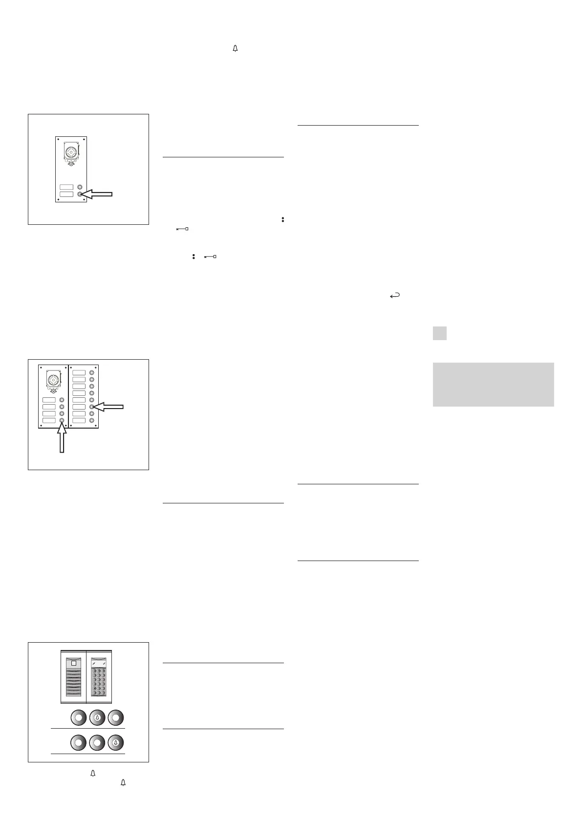
EXAMPLE 5 - Block X2-X1 with entry
panel with AZ/304 or AZV/304 with 10
calls and additional button panels that
usethemoduleVZS/308C(fig.13).
1E
2E
13
1 - Press call button no. 4 (position 1E)
to define the number of buttons used
(4) in the audio/video panel.
Wait for the confirmation note (*).
2 - Then press call button no. 10 (posi-
tion 2E) to define the total number of
user calls used (10).
Wait for the confirmation note (*).
ATTENTION. If the system includes a
porter switchboard, the first button
will automatically be assigned to
the porter call.
EXAMPLE 6 - Block X2-X1 with Targha
digital video entry panel with 20 calls
(fig. 14).
3
1-2
1
2
3
4
5
6
9
8
7
0
C
T
SP
2
0
4
C
14
1 - Type in 4 and (if you are using
the porter call P type in 3 and ).
Wait for the confirmation note (*).
2 - Type in C to cancel the number
shown on the display.
3 - Type in 20 and to define the
total number of users of the block (20).
Wait for the confirmation note (*).
(*) Type of confirmation note
The confirmation note consists of an
acoustic call signal and a double acoustic
signal with activation of the solenoid lock
command.
2 - PROGRAMMING
INTERNAL EXTENSIONS
2.1 - Access internal extension pro-
gramming (the yellow LED flashes
steadily).
2.2 - Lift the receiver of the internal
extensiontobeprogrammed.
Ifthereisahands-freeinternalextension,
simultaneously press the two buttons
and
so that the audio automatically
activates, going directly to point 2.4.
2.3 - Simultaneously press the two but-
tons and of theinternalextension
for at least 1 s;
the unit inserts with the 300 or porter
(entry panel no. 1, default).
2.4 - Make the call from the entry panel
or IPD/300LR if set up;
when programming is complete, there is an
acoustic signal in the internal extension.
2.5 - End communication by hanging
up the microtelephone or pressing the
hands-free button.
2.6 - Repeat the procedure in points
2.2, 2.3 and 2.4 for all internal exten-
sions.
2.7 - Exitprogramming.
NOTE. It is possible to change the default
internal extension used for program-
ming users by choosing any 300 entry
panel or possibly the switchboard IPD/
300LR (see chapter 6).
If you select programming of internal exten-
sions from blocks X2-X1, follow the instruc-
tions attached to entry panel X2-X1.
3 EXIT FROM
PROGRAMMING
Exiting programming (internal exten-
sions or entry panels) includes auto-
matic acknowledgement of any porter
switchboard IPD/300LR or accessories
IOD/300LR present in the system.
At the end of each exit from pro-
gramming, the yellow LED comes on
for about 1 s to indicate that the
automatic programming operation is
complete.
Exiting programming is confirmed when
the LED is off.
4 AUTOMATIC PROGRAMMING
OF POSSIBLE IPD/300LR AND
IOD/303LR WITH NO ENTRY
PANELS
In systems with no 300 or X2-X1 entry
panels, programming of an IPD/300LR
requiresacycleofaccessingandexit-
ing programming.
5 PROGRAMMING OF SLAVE
ENTRY PANELS X2X1
This procedure is to be carried out after
programming of the units described in
point 1.
5.1 - Go to the Master entry panel of
the block.
5.2 - RemovejumperSW1oftheMas-
ter entry panel.
5.3 - Waitfortheacousticconfirmation.
The number of acoustic notes is equal to
the total number of X2-X1 entry panels
connected to the block. However, you may
have to wait 3 to 15 seconds for the acous-
tic confirmation.
5.4 - PutjumperSW1backinplace.
6 MODIFICATION OF THE DEVICE
FOR PROGRAMMING DEFAULT
USERS
It is possible to select the device from
whichtoprogrammetheinternalexten-
sions before activating programming of
theinternalextension.
ATTENTION. Modification of the user
programming device may be done
only after programming the entry
panels (chapter 1) and/or switch-
board IPD/300LR (chapters 3 and 4).
Proceedasfollows:
6.1 - Activate programming of the
internalextensions.
- From the 300 entry panel that you
plan to use for programming, make a
calltoanyinternalextension.Anacous-
tic note confirms this operation.
- To use the porter switchboard IPD/
300LR, make any call (e.g. 1 + ), then
press the function key F1 (an acoustic
note confirms the operation).
6.2 - Proceed with programming of the
internal extensions starting from point
2.2.
ATTENTION. The selector VSE/301
programming procedure, if present,
must be performed only after you
have programmed which calls from
the entry panels are to be associ-
ated with which extensions.
NOTE. Once the power supplier has
been programmed using the PCS/300
unit, the entry panels standard pro-
gramming is no longer accessible.
7 RESETTING
DEFAULT CONDITIONS
7.1 - Activate programming of the
internalextensions.
the LED flashes.
7.2 - Press and hold the SERVICE button
for at least 15 s;
the LED goes off.
8 AUTOTEST
This service can be used to check the
installed system concerning the correct
connections of the audio and video
systems and the correct operation of
the LON devices (entry panels, porter
switchboards, etc.).
8.1 - To enter autotest mode, press the
SERVICE button twice for about 1 s, with
amaximumof3sbetweenthefirstand
second push.
The operation is signalled by prolonged
illumination of the LED followed by a brief
pause.
8.2 - Briefly push the SERVICE button to
exitautotestmode.
the LED goes off.
To use this service, contact BPT tech-
nical service.
MALFUNCTIONS CAUSED BY INCOR-
RECT PROGRAMMING
1 - Video distorted or with poor con-
trast:
- no programming of entry panels;
- inverted polarity of video twisted pair;
- incorrect position of jumper HAV/200
(T position in correct).
2 - Audio disturbance (whistling, low
volume):
- no programming of entry panels;
- no connection of a wire of the audio
twisted pair;
- audio adjustments of entry panel
require calibration.
DISPOSAL
Do not litter the environment with pack-
ingmaterial:makesureitisdisposedof
according to the regulations in force in
the country where the product is used.
When the equipment reachesthe end
of its life cycle, take measures to ensure
it is not discarded in the environment.
The equipment must be disposed of
in compliance with the regulations in
force, recycling its component parts
wherever possible.
Components that qualify as recyclable
waste feature the relevant symbol and
the material’s abbreviation.
D
INSTALLATIONS-
ANLEITUNG
Achtung
Vor der Installation des Gerätes, auf-
merksamdie“INSTALLATIONSHINWEI-
SE”, die der Packung beiliegen, durch-
lesen.
NETZGERÄT XA/301LR
Versorgungs- und Steuereinheit, mit
ECHELON-Bus, der die Erstellung von
Anlagen des Systems 300 Standard und
fürWohngebäudeermöglicht.
Erklaubt die Beibehaltung der Außen-
station, der Innensprechstelle und der
Pförtnerzentrale.
Regelt die Betriebssteuerungen (auto-
matische Einschaltung/Wahl der
Außenstationen,Türöffner,Treppenlicht,
Zusatzsteuerung/Pförtnerruf ) und das
Besetztzeichen.
Für die Datenleitungen zu den Haupt-
und/oder Blockaußenstationen, kom-
muniziert das Gerät über das LON
TALK-Protokoll,während für die Innen-
sprechstellen ein BPT X2-X1-Protokoll
TECHNOLOGY benutzt wird.
Der Verbindungsbus zu den Außenstatio-
nen besteht aus 3 Telefonschleifen plus
Versorgung falls Video vorhanden ist,
währendsichbeiAudiodieVerbindung
aus 2 Telefonschleifen plus Versorgung
zusammensetzt. Der Verbindungsbus
zu den Innensprechstellen besteht aus
einer einzigen Telefonschleife (System
X1) oder aus einer Telefonschleife plus
Versorgung (System X2).
Das Gerät verfügt über einen CNV -
Verbinder für den Anschluss an den
Videomodulator XAV/300 und einen
CNS - Verbinder für den Anschluss an
denWählschalterICB/300.
Verträglichkeit mit XA/300LR
Eventuelle Probleme der Unverträgli-
chkeit (zum Beispiel Verwendung von
VSE/300 oder Innensprechstellen des
 Loading...