4
Brake Valve — A hydraulic counterbalance valve is usually bolted to the hoist port of the hydraulic motor. It allows oil
to ow freely through the motor in the hoisting direction. When oil pressure tries to rotate the motor in the lowering
direction, the brake valve blocks the ow of oil out of the motor until the internal static brake is released. It then controls
lowering speed based on the load and ow of oil to the motor. All the heat generated by controlling the speed of the
load is dissipated by the hydraulic system, not by the internal static brake.
Sprag or Overrunning Clutch — A mechanical one-way clutch on the input shaft of the hoist, between the input shaft
and the static mechanical brake. The clutch allows the input shaft to turn freely in the direction required to spool cable
onto the drum (such as lift a load), then immediately locks the hoist gear train to the mechanical brake when the hoist
is stopped, holding the load in place.
Static, Mechanical, or Load-holding Brake — A multidisc, spring applied, hydraulically released brake that works
together with the sprag clutch to hold a suspended load. This brake is not designed to stop a load being lowered, but
holds the load in place when the hoist is not being operated.
First Layer Line Pull Rating — The maximum rated line pull (in pounds or kilograms) on the rst layer of cable. The
maximum rating for any particular hoist is based on maintaining an acceptable structural design factor and service life.
Certain combinations of drum, gear ratio, motor and hydraulic pressure, may reduce this rating.
First Layer Line Speed Rating — The maximum rated line speed (in feet or meters per minute) on the rst layer of
cable. Certain combinations of drum, gear ratio, motor and hydraulic ow may reduce or increase this rating.
D/d Ratio — The ratio of cable drum barrel diameter (D) to wire rope diameter (d). Current ANSI standards require a
minimum of 17:1.
EXAMPLES:
If you know the cable diameter you want to use, multiply it by 17 to get the MINIMUM cable drum barrel diameter. (such
as 1/2-inch wire rope X 17 = 8.5 inches — this is the minimum hoist barrel diameter)
If you know the barrel diameter, divide it by 17 to get the MAXIMUM wire rope diameter.
(such as 10-inch barrel diameter / 17 = 0.588, or 9/16-inch — this is the maximum wire rope diameter)
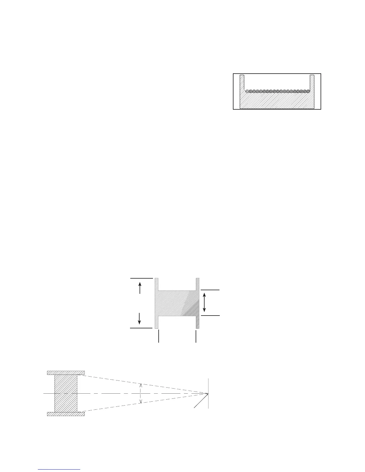
Cable Drum Dimensions —
a
b
First sheave
GLOSSARY
First sheave or load should be cen-
tered between the drum anges, so
that angle A and angle B are equal.
Angles A and B should be a minimum
of 1/2 degree and a maximum of 1-1/2
degrees.
Wrap — A single coil of wire rope wound on a drum.
Layer — All wraps of wire rope on the same level between drum anges.
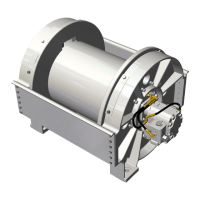
Freeboard — The amount of drum ange that is exposed radially past the last layer of wire rope. Minimum freeboard varies with
the regulatory organization. ASME B30.5 requires 1/2-inch minimum freeboard.
Grooved Drum — A cable drum with grooves on the barrel to ensure the
rst layer of cable spools properly onto the drum. The grooves can be cast
or machined into the drum, or cast or machined into separate pieces that are
mechanically fastened to the drum.
NOTE: Only one size cable can be used on a grooved drum.
Barrel
Diameter
Flange
Diameter
Distance
Between
Flanges
Fleet Angle — The angle between the wire rope’s position at the extreme end wrap on a drum, and a line drawn per-
pendicular to the axis of the drum, through the center of the nearest xed sheave or load attachment point.