Inlet Shut-off Valve Installation
-53-
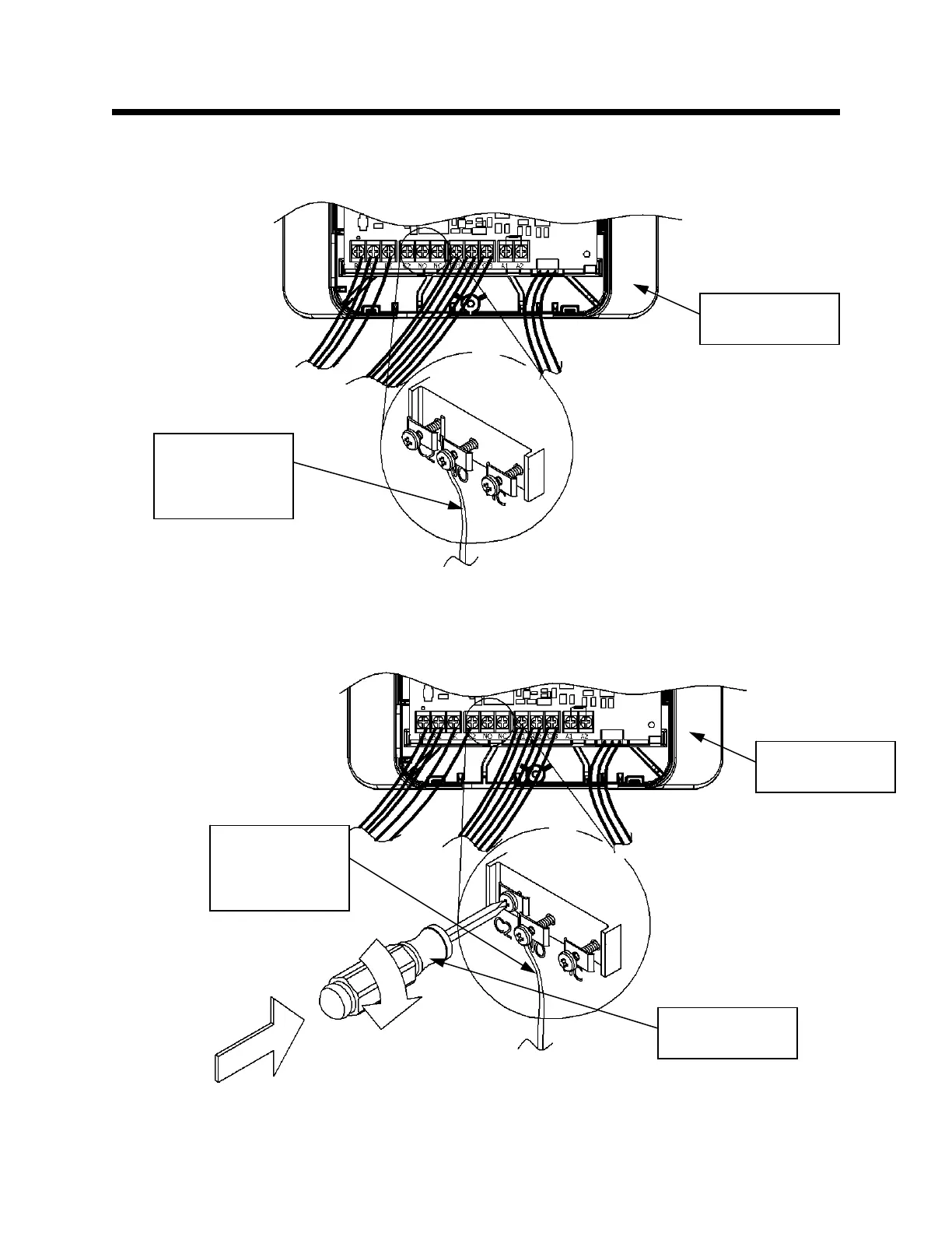
Assemble the Inlet Shut-off Valve Wire Harness and the Accessory Module
Step 9: Insert the blue wire, from the Inlet Shut-off Valve wire harness, under the screw labeled “C2,” as
shown in Figure 76.
Connect the Inlet Shut-off Valve Wire Harness to the Accessory Module
Step 10: Tighten the screw labeled “C2.” This is shown in Figure 77.
Fi
ure 76
Figure 77
Accessory
Module
Inlet Shut-off
Valve Wire
Harness Blue
Wire
Accessory
Module
Inlet Shut-off
Valve Wire
Harness Blue
Wire
Philips head
screwdriver
 Loading...