EasyManua.ls Logo

Bradford White LAARS OmniTherm OCH1250 User Manual

Bradford White LAARS OmniTherm OCH1250
140 pages
To Next Page IconTo Next Page
Page #1 background imageLoading...
Page #1 background image
Document 1464
FOR YOUR SAFETY: This product must be installed and serviced by a professional service technician, qualied
in hot water boiler and heater installation and maintenance. Improper installation and/or operation could create
carbon monoxide gas in ue gases which could cause serious injury, property damage, or death. Improper
installation and/or operation will void the warranty.
H2408400-
WARNING
If the information in this manual is not followed
exactly, a re or explosion may result causing
property damage, personal injury or loss of life.
Do not store or use gasoline or other ammable
vapors and liquids in the vicinity of this or any
other unit.
WHAT TO DO IF YOU SMELL GAS
Do not try to light any unit.
Do not touch any electrical switch; do not use
any phone in your building.
Immediately call your gas supplier from a
nearby phone. Follow the gas supplier's
instructions.
If you cannot reach your gas supplier, call the
re department.
Installation and service must be performed by
a qualied installer, service agency, or gas supplier.
AVERTISSEMENT
Assurez-vous de bien suivres les instructions
données dans cette notice pour réduire au minimum
le risque d’incendie ou d’explosion ou pour éviter
tout dommage matériel, toute blessure ou la mort.
Ne pas entreposer ni utiliser d’essence ni d’autres
vapeurs ou liquides inammables dans le voisinage de
cet appareil ou de tout autre appareil.
QUE FAIRE SI VOUS SENTEZ UNE ODEUR DE GAZ:
Ne pas tenter d’allumer d’appareils.
Ne touchez à aucun interrupteur. Ne pas vous servir des
téléphones dansle bâtiment où vous êtes.
Appelez immédiatement votre fournisseur de gaz depuis
un voisin. Suivez les instructions du fournisseur.
Si vous ne pouvez rejoindre le fournisseur de gaz,
appelez le service des incendies.
L’installation et l’entretien doivent être assurés par un
installateur ou un service d’entretien qualié ou par le
fournisseur de gaz.
Installation and Operation Instructions
Boiler Water Heater
Model OCH1250 Model OCV1250
1,250 MBTU/h 1,250 MBTU/h
Model OCH1500 Model OCV1500
1,500 MBTU/h 1,500 MBTU/h
Model OCH1750 Model OCV1750
1,750 MBTU/h 1,750 MBTU/h
Model OCH2000 Model OCV2000
2,000 MBTU/h 2,000 MBTU/h
Model OCH2500 Model OCV2500
2,500 MBTU/h 2,500 MBTU/h
Model OCH3000 Model OCV3000
3,000 MBTU/h 3,000 MBTU/h
Installation and Operation Instructions for
®
OMNITHERM
with Laars Linc
®
Category II and IV Venting

Table of Contents

Question and Answer IconNeed help?

Do you have a question about the Bradford White LAARS OmniTherm OCH1250 and is the answer not in the manual?

Bradford White LAARS OmniTherm OCH1250 Specifications

General IconGeneral
Fuel TypeNatural Gas or Propane
Input BTU/h1, 250, 000
Ignition TypeElectronic
Input Rating1, 250, 000 BTU/h
Warranty10 years heat exchanger, 1 year parts

Summary

OMNITHERM Installation and Operation Instructions

Product Overview and Safety Information

Details the OMNITHERM product line, categories, and critical safety warnings for installation and operation.

Section 1 General Information

Introduction, Warranty, and Model Identification

Covers the manual's purpose, warranty details, and how to identify different OMNITHERM models.

Section 1 General Information

Unit Dimensions and Components

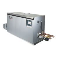
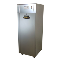
Details the physical dimensions and lists the key components of the OMNITHERM units.

Section 1 General Information

Unpacking, Location, and Clearances

Provides instructions for unpacking the unit, selecting an installation location, and required clearances.

Section 2 Venting and Combustion Air

General Venting Info, Sizing, and Materials

Covers venting principles, pipe sizing guidelines, and acceptable materials for installation.

Section 2 Venting and Combustion Air

Exhaust Vent Terminals and Air Intake Requirements

Details requirements for exhaust vent terminals and combustion air intake configurations.

Section 2 Venting and Combustion Air

Common Venting and Outdoor Installation

Discusses common venting procedures and considerations for outdoor unit installations.

Section 3 Gas Supply and Piping

Gas Supply, Piping, and Sizing

Covers gas supply requirements, piping guidelines, and gas pipe sizing for proper installation.

Section 4 Water Flow and Headloss Data

Water Flow and Headloss Information

Explains water flow principles and provides headloss data for boiler and water heater operation.

Section 5 Piping

Boiler and Water Heater Piping

Details piping requirements for boiler water systems and water heater connections.

Section 5 Piping

Suggested Boiler Piping Schematics

Presents schematic diagrams for various boiler piping configurations and system zoning.

Section 5 Piping

Suggested Water Heater Piping Schematics

Provides schematic diagrams for typical water heater piping setups and tank connections.

Section 6 Condensate Drain Trap

Condensate Management and Safety

Covers condensate drainage, neutralization, and precautions against freezing.

Section 7 Electrical Connections

Installation Warnings and Power Connections

Highlights critical electrical safety warnings and details main power connection requirements.

Section 7 Electrical Connections

Control Panel Layout and Field Connections

Illustrates the control panel layout and outlines field wiring for various components.

Section 7 Electrical Connections

Specific Field Connections and Communication Interfaces

Details connections for pumps, sensors, heat demands, and communication protocols.

Section 7 Electrical Connections

Modbus/BACnet Memory Map

Provides a detailed map of Modbus and BACnet registers for data access.

Section 7 Electrical Connections

High Voltage Wiring Diagrams

Presents wiring diagrams for various high voltage (208V, 480V, 600V) single and three-phase models.

Section 7 Electrical Connections

Ladder Diagrams

Illustrates the control logic diagrams for different electrical configurations.

Section 8 Control Operation

Home Screen, Icons, and Keypad Operations

Explains the main control screen, active icons, and how to navigate using the keypad.

Section 8 Control Operation

Login, Security, and Quick Start Overview

Covers password protection levels and introduces the Quick Start configuration menu.

Section 8 Control Operation

Quick Start Configuration: CH, DHW, Outdoor Reset

Details basic setup for Central Heat, Domestic Hot Water, and Outdoor Reset functions.

Section 8 Control Operation

Quick Start Configuration: Cycle Time, Time/Date

Covers Anti-Short Cycle time adjustment and setting the system's time and date.

Section 8 Control Operation

Configuration Menu Overview

Provides access to all configurable parameters based on the unlocked access level.

Section 8 Control Operation

Central Heat (CH) Configuration Details

Details advanced settings for Central Heat, including PID parameters and set points.

Section 8 Control Operation

Domestic Hot Water (DHW) Configuration Details

Explains advanced settings for DHW, including set points and offsets.

Section 8 Control Operation

Outdoor Reset Configuration

Covers outdoor reset functionality for adjusting set points based on ambient temperature.

Section 8 Control Operation

Cascade Operation Configuration

Details setup for multi-unit cascade systems, including lead/lag logic.

Section 8 Control Operation

Cascade Parameters, Rotation, and Redundancy

Explains how to configure cascade addresses, rotation, and redundancy settings.

Section 8 Control Operation

Pump Control and Vari-Prime Settings

Covers configuration for boiler, DHW, and system pumps, including Vari-Prime control.

Section 8 Control Operation

Manual Firing Rate and Temperature Limits

Allows manual adjustment of firing rate and setting of temperature limits.

Section 8 Control Operation

External Control Configuration

Details how to configure external inputs for BMS or remote set point control.

Section 8 Control Operation

Time & Date and Miscellaneous Features

Covers system time settings and access to features like priorities and warm weather shutdown.

Section 8 Control Operation

Demands Priorities and Anti-Short Cycle

Explains how to set demand priorities and configure anti-short cycle timers.

Section 8 Control Operation

Warm Weather Shutdown and COM Port Settings

Details warm weather shutdown logic and communication port configuration.

Section 8 Control Operation

Temperature Conversion, Anti-Frost, and Login

Covers temperature unit selection, anti-frost protection, and user login procedures.

Section 8 Control Operation

Service Screens Overview and Burner Control

Introduces the service menus and explains burner enable/disable functionality.

Section 8 Control Operation

Digital and Analog I/O Status

Shows the status of digital and analog inputs and outputs for system monitoring.

Section 8 Control Operation

Screen Settings, History, and Restart

Covers display timeouts, operational history logs, and touchscreen restart procedures.

Section 8 Control Operation

Factory Reset and Model Information

Explains how to perform a factory reset and view model/firmware information.

Section 8 Control Operation

Messages and USB Functionality

Details how to view system messages and use the USB port for parameter transfer.

Section 8 Control Operation

Active Demands Display

Illustrates how active heat demands are displayed on the control interface.

Section 9 Gas Valve Touchscreen, Menus and Descriptions

Gas Valve Overview and Navigation

Introduces the gas valve's touchscreen interface and navigation structure.

Section 9 Gas Valve Touchscreen, Menus and Descriptions

Gas Valve Settings and Diagnostics

Covers accessing valve settings for adjustment and diagnostic information for troubleshooting.

Section 9 Gas Valve Touchscreen, Menus and Descriptions

General Settings Menu

Details parameters within the General settings menu, such as valve body and Modbus address.

Section 9 Gas Valve Touchscreen, Menus and Descriptions

Fuel Air Ratio & Ignition Menus

Explains menus for combustion setup, A/F ratio curves, and ignition characteristics.

Section 9 Gas Valve Touchscreen, Menus and Descriptions

Ignition, Curve Adjustments, and Saving Settings

Covers ignition parameters, correction curve adjustments, and saving configurations.

Section 9 Gas Valve Touchscreen, Menus and Descriptions

Gas Valve Diagnostics

Details the diagnostics section for identifying and diagnosing gas valve issues.

Section 9 Gas Valve Touchscreen, Menus and Descriptions

Verification Menu

Describes the required process for verifying safety parameter changes.

Section 9 Gas Valve Touchscreen, Menus and Descriptions

Gas Valve Password and Login

Explains how to access password-protected parameters and manage login credentials.

Section 10 Parameter Tables

OCH (Boiler) Parameter Table

Provides a comprehensive table of parameters, ranges, and defaults for OCH boilers.

Section 10 Parameter Tables

OCV (Water Heater) Parameter Table

Provides a comprehensive table of parameters, ranges, and defaults for OCV water heaters.

Section 11 Initial startup Instructions

Filling the Boiler System

Step-by-step guide for filling and preparing the boiler system for operation.

Section 11 Initial startup Instructions

Initial Operation, Shutdown, Restart, and Combustion Setup

Covers initial burner operation, unit shutdown/restart, and combustion setup procedures.

Section 11 Initial startup Instructions

Firing Rate and Combustion Adjustment

Details how to set the firing rate and adjust combustion via the gas valve display.

Section 12 Maintenance

System Maintenance Schedule and Notes

Outlines annual and semi-annual maintenance tasks, warnings, and general notes.

Section 12 Maintenance

Component Maintenance: Burner, Gas Valve, Controller

Provides procedures for maintaining key components like the burner, gas valve, and controller.

Section 12 Maintenance

Component Maintenance: Blower, Heat Exchanger, Gas Switches

Details maintenance for the blower, heat exchanger, and gas pressure switches.

Section 13 Troubleshooting

Error Codes and Corrective Actions

Lists common error codes, their information, and recommended corrective actions.

Section 13 Troubleshooting

Sensor and Flow Switch Faults

Covers troubleshooting for sensor issues (outlet, inlet, stack) and flow switch errors.

Section 14 Replacement Parts

General Information and Component Illustrations

Provides guidance on ordering parts and includes illustrations of key assemblies and their part numbers.

Related product manuals