
J
Jennifer CohenSep 12, 2025
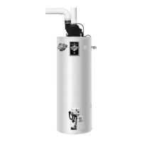
What does six-three flashes on my Bradford White Water Heater mean?
- LLorraine RileySep 12, 2025
This could be caused by an unstable pilot, a blocked or restricted pilot tube, oxidation build up on the pilot electrode, wire damage to pilot assembly or a bad connection at the gas valve, insufficient combustion air, or gas pressure out of specification.