EasyManua.ls Logo

Bradley S19-320 - Page 5

Default Icon
22 pages
Print Icon
To Next Page IconTo Next Page
To Previous Page IconTo Previous Page
Loading...
ON
OFF
DUST COVER
STROBELIGHT
ALARM HORN
PLATE
(qty. 2)
NUT
(qty. 4)
U-BOLT
(qty. 2)
ALARM HORN
CUT-OUT SWITCH
WATERPROOF CABLE WITH
QUICK-CONNECT COUPLING
POWER
SUPPLY
ALLEN SCREW
(qty. 2)
WATERPROOF
JUNCTION BOX
FLOW
SWITCH
ARROW MUST
POINT IN
DIRECTION
OF FLOW
RED
BLUE
BLACK
REMOTE SENSING
SWITCH
STROBE
POWER SUPPLY
RED
WHITE
HORN
SOCKET
GRAY
GRAY
GREEN
BLACK
ELECTRICAL
CONNECTIONS
IMPORTANT!
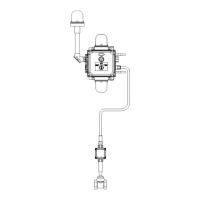
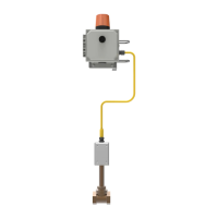
System is prewired. Installer
connects ONLY ground,
black and white wires!
WHITE
1-1/4" HORIZONTAL
SUPPLY
WHITE
GREEN
BLACK
WHITE
Installation Instructions
4. Replace the front grille onto the alarm horn casing being sure the prong plugs (that are part of the
front grille) line up with the socket slots inside the casing.
• Tighten the two 5/64" hex screws.
5
Installation S19-320, S19-320C
Bradley Corporation • 215-693 Rev. H; EN 04-572 2/9/05
P
.O
.
BO
X
3
0
9
,
M
E
N
O
M
O
N
E
E
F
A
L
L
S,
W
I 5
30
5
2
-0
3
0
9
U
S
A
T
E
L
: 1
-8
0
0
-B
R
A
D
L
E
Y
F
A
X
: (2
62
-
25
1
-5
8
1
7
)
h
ttp
://w
w
w
.b
ra
dl
eyc
o
rp
.c
o
m
11
4
-0
52
TO
ELECTRIC
POWER
ALARM
FLOW
SWITCH
TO
WATER
SUPPLY
Figure 1 Figure 2

Related product manuals