14698_r00 13/18
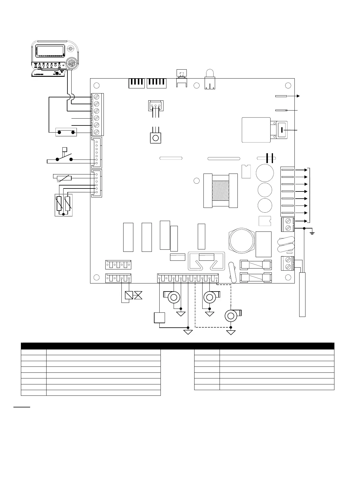
WIRING DIAGRAM FOR BRAHMA DEVICES type TC340
A
.**.**.** opt.
C1 / C2
J12
J11
J10
J19
J8
J7
J6
J3
J5
J4
J2
RESET
J13 J14
out
+5V
GND
SP (Nota 1)
+
-
MARRONE
NERO
BLU
4
3
2
1
4
3
2
1
5
4
3
2
1
5
6
1
2
3
4
5
6
7
1
2
3
4
5
6
1 2 3 4
1 2 3 4
1 2 3 4 5 6 7 8 9
2
1
2
1
2
3
1
PE
PE
Key to symbols
GA1 Chronothermostat type ENCRONO GA1 SA Room temperature probe (optional)
EF Burner motor APS Air pressure switch
FAN Hot air blower STF Fire damper
ACC1 Remote auxiliary ignition transformer SL LED signalling
ACC2 Inbuilt ignition transformer RESET Reset push-button
EV1 BRAHMA valve type VCM01* # (0/P) (0/P) 24VDC EX Connection for cascade appliances
SP VCM01 valve pressure sensor ION Ionization electrode
SR Heating circuit probe
NOTES
1. Connector and wiring not available in C2 version.