14/18 14698_r00
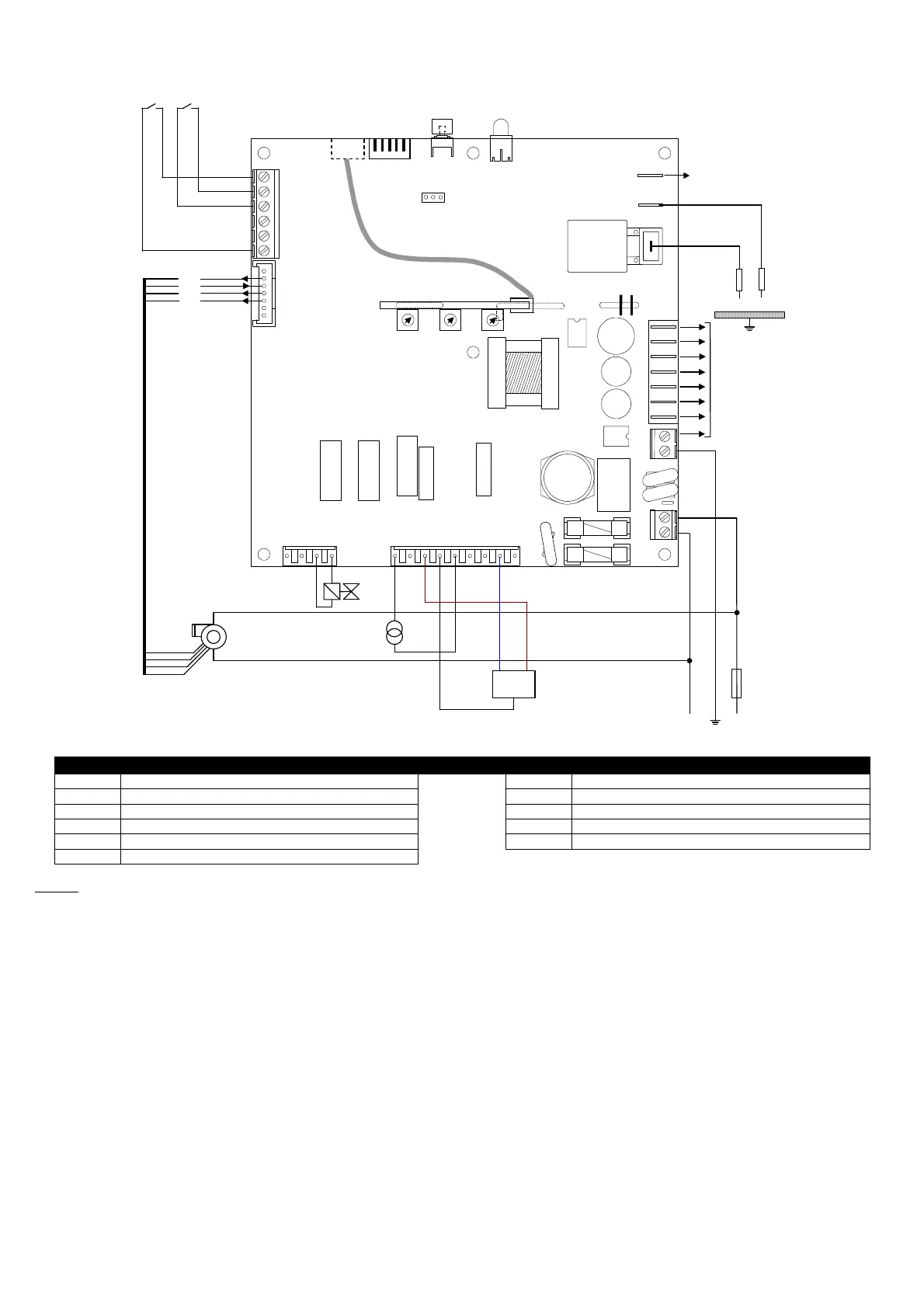
WIRING DIAGRAM FOR BRAHMA DEVICES type TC340
P1
.**.**.** opt. G NT NS
J12
J11
J7
J6
J5
J4
J2
N L
RESET
J14
+24V
RPM
PWM
GND
4
3
2
1
5
4
3
2
1
5
6
1
2
3
4
5
6
7
1 2 3 4 1 2 3 4 5 6 7 8 9
2
1
2
1
ACC2
JP2
T2 TC
P1 P2 P3
+ -
J3
M (Nota 2)
PE
PE
J13
Key to symbols
TC Heat demand room thermostat N1 Three-point adjuster
T2 Adjustment thermostat / BOOST function SL LED signalling
EF Burner motor RESET Reset push-button
ACC1 Remote auxiliary ignition transformer EX Connection for cascade appliances
ACC2 Inbuilt ignition transformer ION Ionization electrode
EV1 First valve stage
NOTES
2. Vertical module for setting up 3 of the 11 modulation parameters (available upon request).