English
@ntrols,
displays, Front
panel
COnngCtiOnS
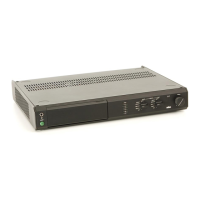
1
"Power"
on/off switch
2
Stereo
headphones
jack
(6.3
mm
jack,
Note: With the
push-button
controls,
the
stereo as
per
IEC 130-8)
desired function is obtained by depres-
sing
the
corresponding button.
The
controls
(3)
to
(13)
can
be found
by
With
all
rotary
controls,
turning to the
opening the front flap.
right
increases their etfect.
3,4 Push-button for loudspeakers 1, 2
or
1and2
5 Push-button
"tone
defeat"
(over-rides
the bass and treble controls)
6 Push-button
"filter
30 Hz"
(subsonic
filter)
7 Push-button
"filter
7.5,, kHz
(high
cut)
8 Push-button
..mono'
9 Push-button
"linear"
(switches
the loud-
ness
compensation out)
10 Push-button
"display
sens>
(increases
the
sensitivity of the LED
display
(14))
11 Rotary
control
,.bass,
12 Rotary
control
"treble'
13 Rotary
control
"balance"
with a centre
location
point
14 2 LED displays
(for
left
and
right
chan-
nel) with the following markings:
.,on,,
is illuminated in
green
when the
power
is
switched on
"16-0"
level
indicators
(green)
for
both
channels
in dB
"clipo
(clipping)
illuminates red when
the
power
amplifier
is
overloaded.
15 Rotary
switch
"record
selector" selects
the
source to be
recorded.
16 Rotary
switch
"input
selector" selects
the source which will be heard through
the loudspeakers.
17 Rotary
control
..volume'
Back
of amplifier
18 Earthing
screw
"phono
+"
(for
the turn-
table
earth
lead)
19
"phono"
sockets to connect turntable 1
20
"phono"
sockets to connect turntable 2
21
"tuner"
sockets
22,,aux,,
sockets to connect another signal
source e.g.a microphone
amplifier
(see
technical data regarding
signal strength
and impedance)
23
"tape
1 in"
sockets
(tape
or
cassette deck
1)
24
"Iape
1
out" sockets
(tape
or cassette deck 1)
25
"tape
2 in" sockets
(tape
or cassette deck 2)
26
"tape
2 out"
sockets
(tape
or cassette deck 2)
27,,pre-out"
(p
re-ampl ifier
output)
28
"main-in"
(power
amplifier
input)
Note:
Sockets
(27)
and
(28)
are con-
nected
according to
channel by
means
of a
jumper.
29 Push-in
connectors
"speakers
1"
30 Push-in
connectors
"speakers
2"
31 AC
power
cable
32 Grooves for fixing
back cover
33 Indentations for locating the feet
of unit
placed
on top
All
cinch sockets at the
back of the
amplifier are in accordance with IEC
Spec.130-8
 Loading...