D124.1S2-Manual_EN_Rev03
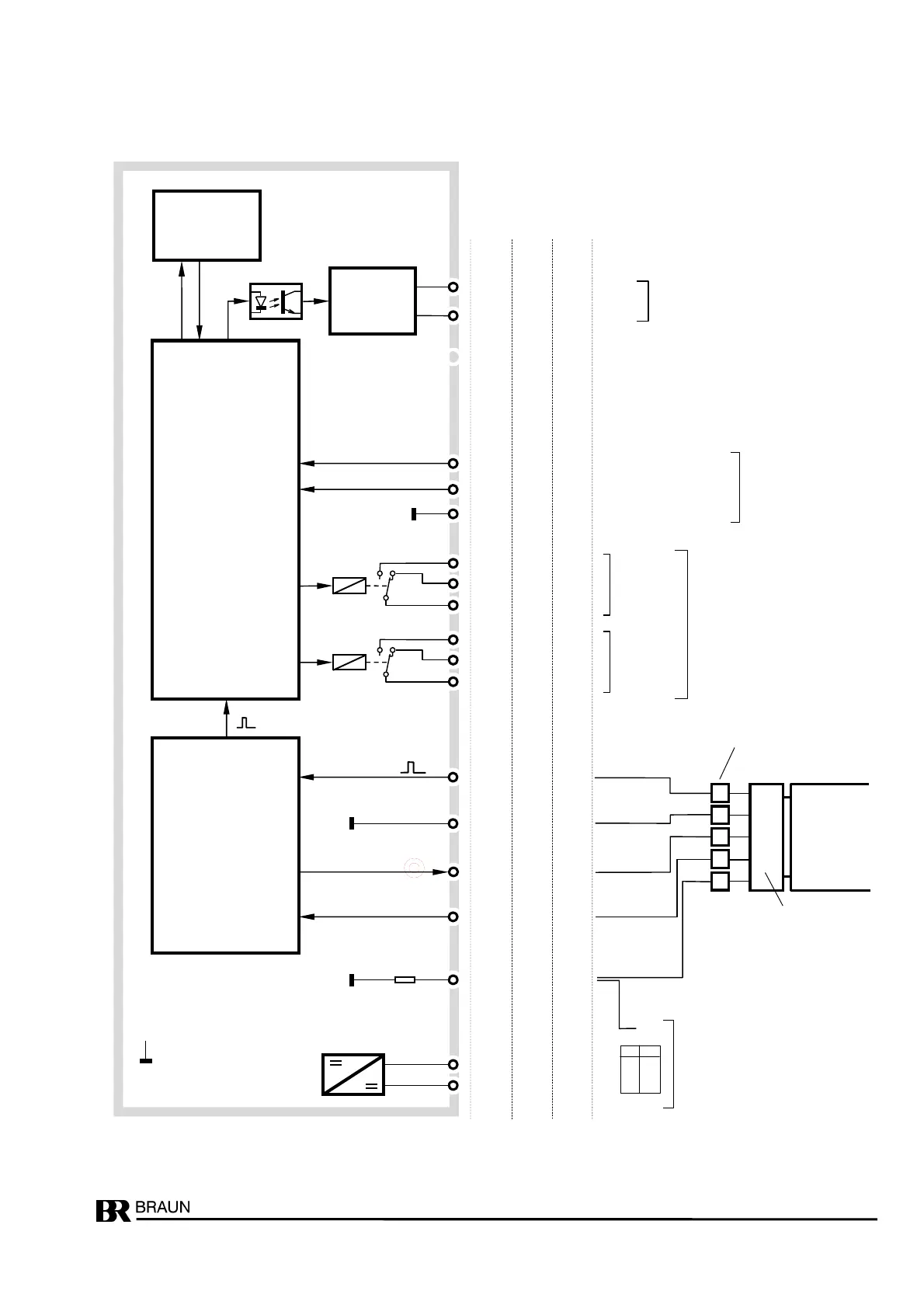
Function diagram and terminal nos.
Measurement
and
signal
processing
D/A-converter
and
output stage
D124
C10
C9
19
18
+
Analog output
0/4..20mamps
Contacts shown for de-energized
relays
capacity maximal 250V/2A/100W
use spark extinguisher with inductive
18b
18z
B3 24 12b
power-
supply
U1: 18....40V uc
U2: 85..265V uc
observe type label
S1 : high = starter signal
Display
and
keys
reference
control inputs
high = level
+10..+24volts vs
ref
or contact closure
vs "sensor supply
Input
sensor
supply
Sensor supply
100 k
A2
A1
A3
1
2
38
screen (not connected to sensor
PE
dc ac
+ L1
32b
32z
8b
C2
C3
C1
5
4
3
relay SP1
setpoint alarm
or
reverse alarm
20b
22b
24b
C5
C6
C4
8
7
6
reverse alarm
SP2
26b
28b
30b
+12V / max. 60 mA
A5 32 10z
B2 26 10b
A10 20 24z
B1 25 12z
Direction signal
S2 : high =reset of reverse
A10 31 8z
0V
Common ref.
A12 37 2b
Frequency signal
= internal zero, isolated
from power supply
A
B
C
S
A5S3...
D
V / R
Marked cable ends of BRAUN
cables
4
2
1
3
connector pins