36 of 52© 2021 BRAY INTERNATIONAL, INC. ALL RIGHTS RESERVED. BRAY.COM EN_TSM-2004-6A Advanced_Set-Up_20211012
SERIES 6A
ADVANCED SETUP GUIDE
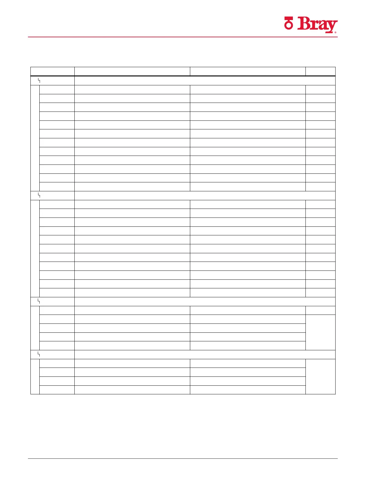
8.4 Overview of diagnostic parameters
Parameter Function Parameter values Unit
A.
PST Partial Stroke Test (PST) with the following parameters:
A1.STPOS Start position 0.0 ... 100.0 %
A2.STTOL Start tolerance 0.1 ... 2.0 ... 10.0 %
A3.STRKH Stroke height 0.1 ... 10.0 ... 100.0 %
A4.STRKD Stroke direction uP / do / uP do
A5.RPMD Ramp mode OFF / On %/s
A6.RPRT Ramp rate 0.1 ... 1.0 ... 100.0
A7.FLBH Behavior after failed PST Auto / HoLd / AirIn / AirOu
A8.INTRV Test interval OFF / 1 ... 365 Days
A9.PSTIN Reference stroke time for PST NOINI/(C)##.#/FdIni/rEAL s
AA.FACT1 Factor 1 0.1 ... 1.5 ... 100.0
Ab.FACT2 Factor 2 0.1 ... 3.0 ... 100.0
AC.FACT3 Factor 3 0.1 ... 5.0 ... 100.0
A.
PST Partial Stroke Test (PST) with option -Z P02 with the following parameters:
A1.STPOS Start position 0.0 ... 100.0 %
A2.STTOL Start tolerance 0.1 ... 2.0 ... 10.0 %
A8.INTRV Test interval OFF / 1 ... 365 Days
Ad.ENPOS End position 0.0 … 90.0 … 100.0 %
AE.ENTOL End tolerance 1.0 … 5.0 … 20.0 %
AF.BOLIM Breakout pressure limit 0.1 … 7.0 bar
AG.BOTOL Breakout pressure tolerance 0.1 … 6.0 bar
AH.PSTDO Time to end position 1 … 80 ... 300 s
AJ.PSTUP Time back to start position 0 ... 300 s
AL.PSTRP Test repetitions 0 ... 3 s
AY.PSTIN Start PST reference "leer" / C-Err / oCAY / noINI / FdIni / SdrEF
b.
DEVI Monitoring of dynamic control valve behavior with the following parameters:
b1.TIM Time constant Auto / 1 ... 400 s
b2.LIMIT Limit 0.1 ... 1.0 ... 100.0 %
b3.FACT1 Factor 1 0.1 ... 5.0 ... 100.0
b4.FACT2 Factor 2 0.1 ... 10.0 ... 100.0
b5.FACT3 Factor 3 0.1 ... 15.0 ... 100.0
C.
LEAK Monitoring/compensation of pneumatic leakage with the following parameters:
C1.LIMIT Limit 0.1 ... 30.0 ... 100.0 %
C2.FACT1 Factor 1 0.1 ... 1.0 ... 100.0
C3.FACT2 Factor 2 0.1 ... 1.5 ... 100.0
C4.FACT3 Factor 3 0.1 ... 2.0 ... 100.0
Parameter assignment
8.4 Overview of diagnostic parameters
SIPART PS2 with 4 to 20 mA/HART
138 Operating Instructions, 10/2020, A5E00074631-AF
5.0 Overview of Diagnostic Parameters

 Loading...

