11
Chapter 1: Hardware insertion.
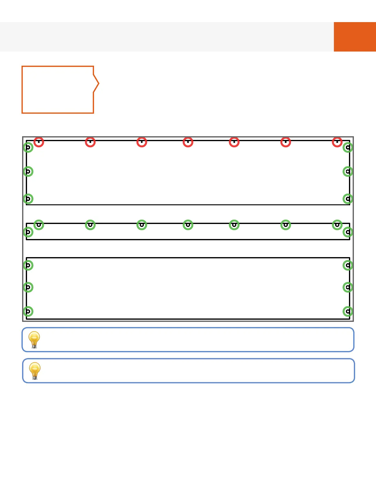
Referring to Fig. 1B, lay parts on oor and insert cam screws
from Hardware Package #1 in holes marked with a red circle
using the cordless drill (see note at the bottom of this page).
Insert cam ttings from Hardware Package #6 in holes
marked with a green circle using the rubber mallet (see note
at the bottom of this page). Cam ttings should be inserted
with the at part of the cam tting ush with the side of the panel.
Headboard
Bed Cabinet Top Nailer
Bed Cabinet Top
FIG. 1B
STEP 2
The quantity of holes for Top and Top Nailer will vary depending on bed size.
Insert cam screws/ttings in each hole along the top of these panels.
When inserting cam ttings, place the panel on a at, solid surface so that
the force of the mallet is distributed evenly to the underlying surface.