BREN 700-Series User Manual
General Information 1-
5
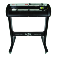
1.4.4 The Left-hand Side (Figure 1-4)
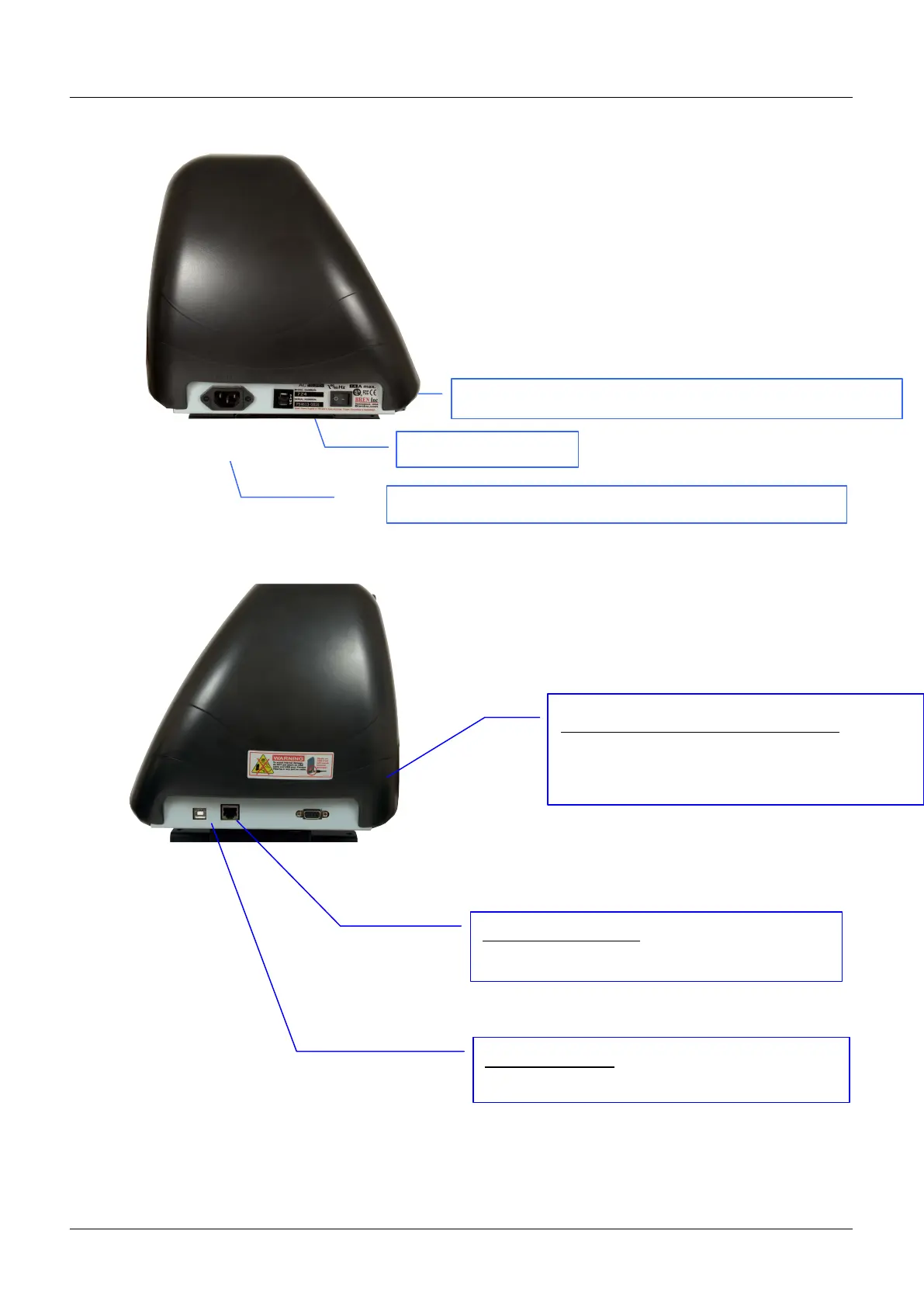
1.4.5 The Right-hand Side (Figure 1-5)
Fuse – 3 Amp.
AC Power Connector – used to insert the AC power cord.
Power Switch – On when switches to [I]; Off to [O]
Figure 1-4
Serial Interface Connector (RS232C) – used
to connect the cutting plotter to a computer
through a serial interface cable.
Figure 1-5
USB Connector – used to connect the cutting
plotter to a computer through a USB cable.
Ethernet Connector– used to connect your
computer to a local area network.
 Loading...