Trigger from vehicle, high active
(Range above +9Vdc, up to supply voltage)
3.4 Sensor Mounting and Location
3.4.1 Sensor Direction
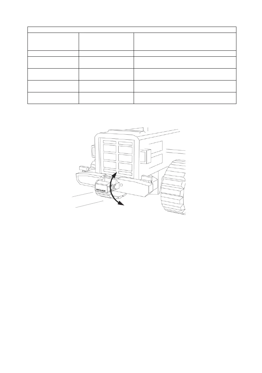
The sensor should be mounted in an upright position with the cable exit on the sensor pointing
downwards, such that the Brigade logo on the front of the sensor is readable when standing in
the required detection area. The front of the sensor should have line of sight to all areas where
objects should be detected.
3.4.2 Sensor Fixing
The unit is supplied with four M5x30mm screws and four M5 polymer locknuts for mounting
purposes. The recommended torque is 6Nm or 50 inch/lbs.
3.4.3 Vehicle Overhang into Detection Area
It is recommended that the mounting position on the vehicle should avoid any vehicle furniture
overhanging into the detection area, as such objects will cause false alarms (for exceptions
refer to section “1.2 Object Detection Capability”, paragraph “Warning”).
The detection area of the Brigade Backsense
®
radar beam has a 140° horizontal angle to the
maximum designated width and a vertical angle of 16°, see section “1.2.1 Detection Pattern”
for details.
 Loading...