15
4 Configuring the BS-7100 System
This section covers how to configure the Brigade Backsense
®
BS-7100 system.
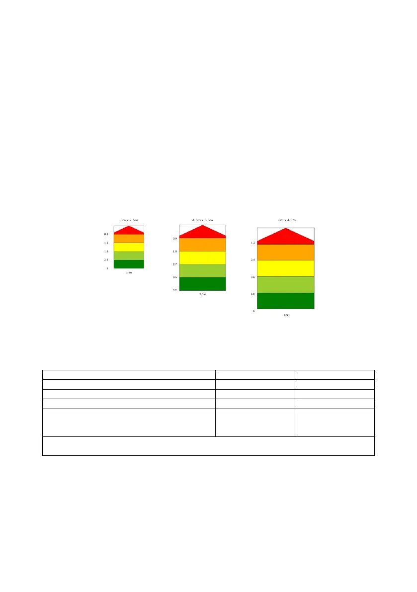
4.1 Detection Zones
1) 5 detection zones. Length of each zone equally divided within the total detection
length.
2) Total Detection Zone Length is fixed at (3m, 4.5m and 6m) and dependent on
display configuration.
3) Detection Zone Width is fixed (2.5m, 3.5m and 4.5m) and dependent on display
configuration.
4) Detection Zones can be selected via Mode configuration wires (Mode 1 and Mode
2)
5) Detection Zone Width is set globally for all 5 zones. See example below showing all
detection zones
4.2 BS-7100D Detection Range Configuration
1) Configuration mode wire logic table:
Selectable Detection Range
6m length x 4.5m width (Default)
Not Used
LED Display will indicate system error if both
mode wires are connected to ground
‘X’ = not active when the Mode wire is floating or connected to 12/24V
‘L’ = active when the Mode wire is connected to GND
2) The BS-7100D display will check the status of mode configuration wire inputs at
start-up only. Any changes in Mode configuration status input states after start-up
and self-check (during normal operation) will be flagged as an error by the LED
display.
3) Ensure the new sensor is configured.
4) Power up the BS-7100 system with Mode 1 and Mode 2 configuration wires
connected as per the table above.
5) The BS-7100D will show (via zone lights) the correct detection mode is selected
during start-up.
 Loading...