Bri_s & Stratton Power Products Home Generator
Installation Manual
INSTALLATION
PROCEDURES
Unpacking Precautions
The unit is shipped bolted to its mounting pad, ready for
installation. Avoid damage from dropping, bumping, collision,
etc. Store and unpack carton with the proper side up, as
noted on the shipping carton.
CAUTION
• Observe that the 15 Amp fuse has been removed from the
control panel for shipping.
• DO NOT install this fuse until all plumbing and wiring has
been completed and inspected.
Delivery Inspection
After removing the carton, carefully inspect the Home
Standby Generator for any damage that may have occurred
during shipment.
IMPORTANT: If loss or damage is noted at time of
delivery, have the person(s) making delivery note all damage
on the freight bill and affix his signature under the
consignor's memo of loss or damage. If loss or damage is
noted after delivery, separate the damaged materials and
contact the carrier for claim procedures. Missing or
damaged parts are not warranted.
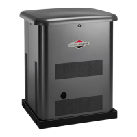
Shipment Contents
The Home Standby Generator is supplied with:
• Home Standby Generator
• Pre-attached mounting pad
• One 24" flexible hook-up hose
• Installation and start-up manual (P/N 192385GS)
• Owner's manual(P/N 192384GS)
• Illustrated parts list manual (P/N 193208GS for
model 01815 or P/N 193918GS for model 01938)
• Product warranty sheet (P/N 190881GS)
• Installation checklist (P/N 190840GS)
• Three access door keys
• Four lifting hole plugs
• Oil fill spout
• Touch-up paint
• One spare 15A fuse
• Diagnostic LED kit (diode/plate/decal/pin connectors (2))
Required Specialty Tools/Equipment
• Two 48" lengths of I" OD pipe (NOT conduit)
• Hole punches for 16ga steel
• Torque screwdriver, 5 to 50 inch-pound range
Approved Transfer Switches
The Home Standby Generator should be used ONLY with
the following UL approved Transfer Switches. Connection
to any other transfer switch not listed below will void your
equipment warranty.
• 50A Nema I enclosure, BSPP Model 01917
• 50A Nema 3R enclosure, BSPP Model 01918
• 100A Nema 3R enclosure, BSPP Model 01813
• 100A Nema 3R enclosure w/main line disconnect, BSPP
Model 01928
• 200A Nema 3R enclosure, BSPP Model 01814
• 200A Nema 3R enclosure w/main line disconnect, BSPP
Model 01929
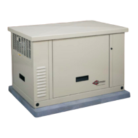
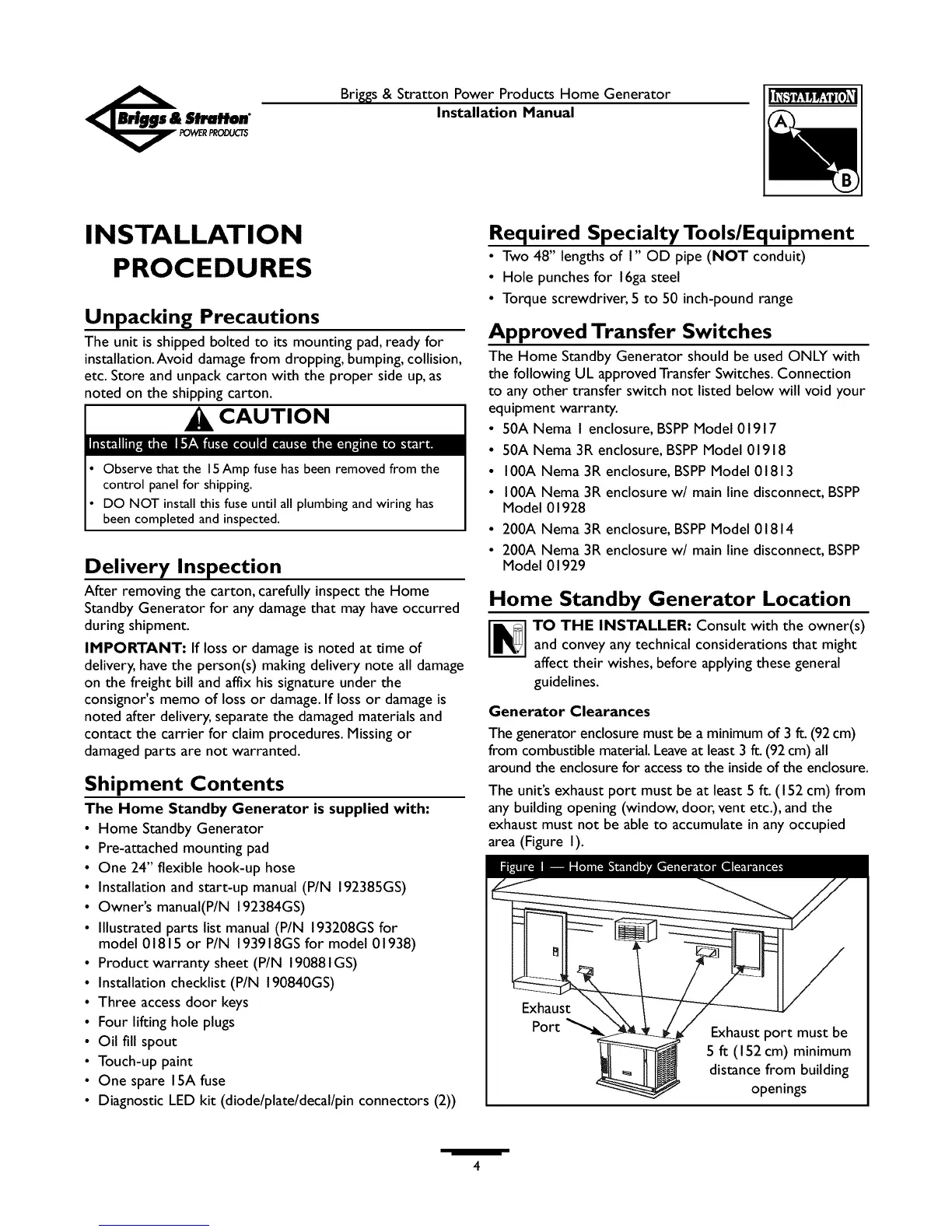
Home Standby Generator Location
TO THE INSTALLER: Consult with the owner(s)
and convey any technical considerations that might
affect their wishes, before applying these general
guidelines.
Generator Clearances
The generator enclosure must be a minimumof 3 ft. (92cm)
from combustible material.Leaveat least3 ft. (92 cm) all
around the enclosurefor accessto the insideof the enclosure.
The unit's exhaust port must be at least 5 ft. (I 52 cm) from
any building opening (window, door, vent etc.), and the
exhaust must not be able to accumulate in any occupied
area (Figure I).
Port
Exhaust port must be
5 ft (I 52 cm) minimum
distance from building
openings
 Loading...