In the USA and Canada, a 24 hour hot line, 1-800-233-3723, has a menu of pre-recorded messages offering you engine maintenance information.
5
Adjustments
Control adjustments
To prevent accidental starting,
remove spark plug wire from spark
plug and disconnect battery at nega-
tive terminal, if equipped, when
adjusting controls.
WIRE
Remote choke control:
Move choke control to CHOKE or START position. Choke
valve should be closed. To assure choke valve is closed, loos-
en casing clamp screw and pull casing, wire and choke lever
in direction of arrow to end of travel. With choke control in
CHOKE or START position, tighten casing clamp screw.
Choke control adjustment
CASING CLAMP
SCREW
To adjust throttle control:
With throttle control in FAST position, hole in governor control
lever (located just behind governor control plate) must align
with hole in governor control plate, as illustrated below. If it
does not, loosen casing clamp screw and then move governor
control rack until it does. Tighten casing clamp screw.
Check stop switch
Move throttle control to STOP position. Governor control lever
must make good contact with stop switch, if equipped.
Check operation of controls. Readjust if necessary.
Throttle control adjustment
HOLE IN
GOVERNOR
CONTROL
PLATE
GOVERNOR
CONTROL
LEVER
STOP
SWITCH
GOVERNOR
CONTROL
RACK
CASING
CLAMP
SCREW
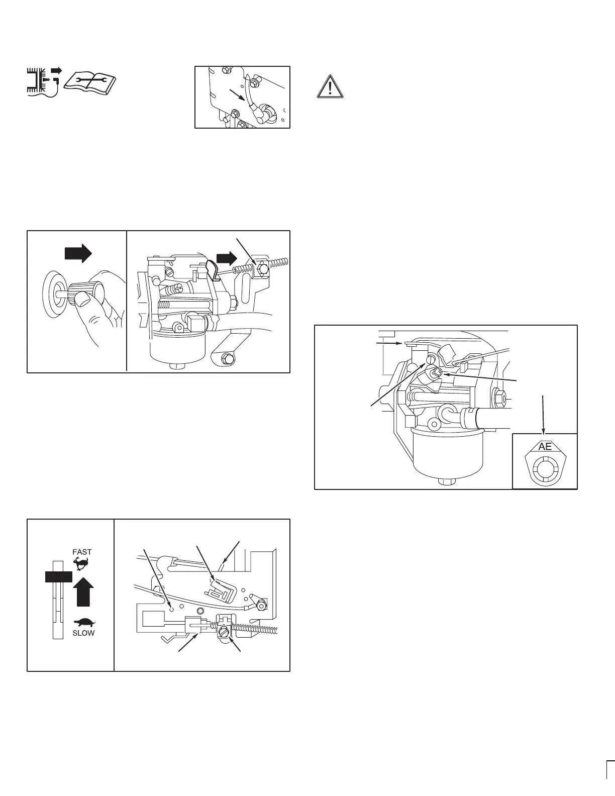
Carburetor adjustments
The manufacturer of the equipment on which this
engine is installed specifies top speed at which the
engine will be operated. DO NOT EXCEED this speed.
Differences in fuel, temperature, altitude or load may require
minor carburetor adjustment. Air cleaner and air cleaner cover
must be assembled to carburetor before starting engine.
The carburetor on this engine is low emission. It is equipped
with an idle mixture valve with a limiter (see inset), which allows
some adjustment, and an idle speed adjustment screw.
Adjustments
Start engine and warm up approximately 5 minutes before
adjusting. With engine running, place throttle control in SLOW
position. Rotate carburetor throttle lever against the idle
speed screw and hold it. Turn idle speed screw to obtain 1750
rpm.
Rotate idle mixture valve full travel clockwise and then counter-
clockwise. Finally, position idle mixture valve in middle of trav-
el. Check idle speed and re-adjust to 1750 rpm, if necessary.
Move throttle control to FAST position. Engine should
accelerate smoothly. If it does not, adjust idle mixture valve
counterclockwise 1/8 turn.
Carburetor adjustments
IDLE SPEED
SCREW
CARBURETOR
THROTTLE
LEVER
IDLE MIXTURE
VALVE
WITH LIMITER
 Loading...