9
Connector tightening torques shall be as follows:
Utility - 5 in-lb (5.5 Nm) Ground - 5 in-lb (5.5 Nm)
Generator - 5 in-lb (5.5 Nm) Control - 1 in-lb (1.4 Nm)
Neutral - 11 in-lb (12.5 Nm)
Fuseblocks - 1 in-lb (1.4 Nm)
Use oxide inhibitor on all aluminum terminations.
All terminal and bus lugs are suitable for copper wire of
60°/75°C rating.
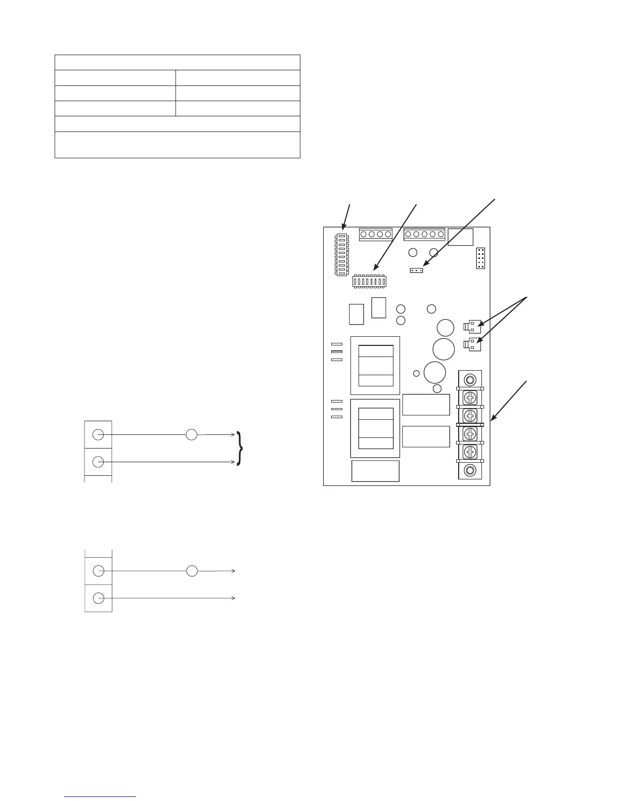
Supervisory Control Wiring
An air conditioner can be used with the supervisory contacts
on either terminals A-A or B-B. Terminals A-A can only be
used with supervisory control. Large loads can only be used
with contactor control on terminals B-B. Examples of each
system are described below.
1. The terminal strip on control module in transfer switch
has four connections for customer use. There are two
sets of “Normally Closed” contacts available. They will
be activated when generator power is required. These
can be used for supervisory control of large connected
loads on generator. Loads will be allowed to operate if
there is enough generator power available.
NOTE: There are two wireways provided to keep the
supervisory loads separated from each other.
2. Terminals “A-A” on control module are rated for
24VACandairconditionercontactorcontrol.Contacts
are connected in series with the air conditioner
contactor control circuit.
3. Terminals “B-B” on control module are rated for 1 Amp
125VACandinstallersuppliedcontactortocontrol
a large load, such as an electric hot water heater.
Contacts are connected in series with the contactor
control circuit.
4. Tighten all wire connections/fasteners to proper torque.
See label inside transfer switch enclosure for proper
torque values.
System Setup
You must perform the following before operating the system:
• Ifgeneratorisinstalledinanarearegularlysubjected
to temperatures below 40°F (4°C), select a 50 second
warm up time by moving jumper installed on JP2 from
‘20’ position to ‘50’ position.
• SettheDPSW1andDPSW2dipswitchesonthecontrol
module to match the KW rating of the home standby
generator, as described in Setting Dipswitches.
Setting Dipswitches
Dipswitches are used to adjust control board operation
based on generator capacity and fuel source. DPSW1 and
DPSW2 switches are set to correspond to total system kW
rating. Dipswitch DPSW1 has units of 1,000 watts; Dipswitch
DPSW2 has units of 10,000 watts.
IMPORTANT: Set only one switch to “On” position on
DPSW1 and DPSW2.
A
A
Air Conditioner Contactor
24VAC
B
B
Contactor
Neutral
120VAC
JP2
DPSW1
Dipswitch
CT1 & CT2
Connectors
Supervisory
Contacts
DPSW2
Dipswitch
NOTICE Use extreme caution when setting dipswitches or
damage to control board will result.
Use a pencil or small piece of plastic to set the dipswitch.•
NEVERuseascrewdriveroranytypeofmetalobjectto•
set dipswitches.
 Loading...