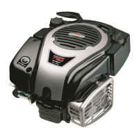
Do you have a question about the Briggs & Stratton 700 DOV Series and is the answer not in the manual?
| Fuel Type | Gasoline |
|---|---|
| Starting System | Recoil |
| Displacement | 161 cc |
| Oil Capacity | 20 oz |
| Engine Type | 4-Stroke, OHV, Single Cylinder |
Provides essential safety information regarding engine operation and maintenance.
Covers routine maintenance procedures and recommendations for the engine.
Details on oil changes, air filter cleaning, and spark plug replacement.
Procedures for maintaining the cooling system and charging batteries.
Instructions for removing deposits from the engine's combustion chamber.
Procedures for adjusting engine components for optimal performance.
Guides for adjusting throttle cable and governor system settings.
Steps to adjust valve clearance and the ReadyStart choke link.
Procedure for setting the air gap for the armature.
Procedure for setting the air gap for the alternator.
Information on the flywheel brake system, including testing and removal.
Overview of common engine complaints and a systematic approach to diagnosis.
Procedures for testing the engine's ignition system for proper function.
Steps to check the fuel system (carburetion) and engine compression.
Details on testing electrical components like multimeters, tachometers, and shunts.
Procedure for testing the engine's alternator output and components.
Diagnosing and testing the electric starter motor and its components.
Guidance on testing battery health, capacity, and proper installation.
Diagram and components of the engine's exhaust system.
Procedures for removing, inspecting, and installing the muffler guard and muffler.
Steps for removing, inspecting, cleaning, and installing the fuel tank.
Procedures for removing, disassembling, inspecting, cleaning, and assembling the carburetor.
Diagram and components of the engine's governor system.
Details on governor linkage orientation, spring replacement, and checking top RPM.
Procedures for disassembling, inspecting, and assembling governor components.
Diagram of cylinder head and valve components.
Steps to remove the cylinder head and disassemble its components.
Procedures for inspecting cylinder head components and reassembling.
Diagram of the electric starter motor and its parts.
Procedures for disassembling, inspecting, and assembling the electric starter drive.
Diagram of the rewind starter mechanism and its parts.
Instructions for inspecting rewind starter parts and replacing the starter rope.
Diagram of the engine's lubrication system components.
Details on the oil fill tube, dipstick, and their replacement.
Procedures for removing, checking, and installing the breather valve system.
Guidance on lubricating and inspecting the oil slinger and governor gear.
Diagram of the cylinder and sump components.
Procedures for inspecting, reconditioning, and cleaning the cylinder bore.
Steps for inspecting and cleaning the engine sump.
Information on inspecting main bearings and installing oil seals.
Diagram of the crankshaft and related components.
Steps for removing and inspecting the crankshaft for damage and wear.
Procedures for installing the crankshaft and checking/adjusting end play.
Diagram of piston, rings, and connecting rod components.
Steps for removing the piston and connecting rod from the cylinder.
Procedures for inspecting piston, pin, connecting rod, and ring end gap.
Steps for assembling the piston, rings, and connecting rod.
Engine and fastener torque specifications for Model 090600.
Standard and reject dimensions for cylinder, head, rod, piston, and starter rope.
Engine and fastener torque specifications for Model 100600.
Engine and fastener torque specifications for Model 100800.




 Loading...