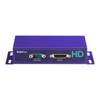
BrightSign HD222, HD1022
12
All information provided in this reference manual applies to products under development. The characteristics and specifications of these products are subject to
change without notice. BrightSign assumes no obligation regarding future manufacturing unless otherwise agreed to in writing. © BrightSign LLC, 2015
THEORY OF OPERATION
This section describes how specific components operate on the HD222 and HD1022.
BCM7241 CPU
The HD222 and HD1022 utilize a BCM7241 CPU. The CPU is reset by the RESET_L signal from the low voltage reset
circuit going into the RESET_IN pin on the CPU. When the RESET_IN pin goes from low to high, the CPU will boot from
the NAND flash.
Built-in Flash
The boot code in the BCM7241 instructs it to continue the boot process by reading additional code from the onboard
NAND flash, which can be updated in the field, either from a SDHC/SDXC flash card or a USB mass-storage device. Part
of the NAND flash is also used to hold non-volatile parameters. The contents of the boot flash are copied into the SDRAM.
The CPU then jumps to the boot code.
SDRAM
The HD222 and HD1022 contain a single bank of DDR SDRAM, consisting of two 16x256MB chips (1GB total). When the
CPU boots, it will copy the code from the NAND flash device into the SDRAM and then execute the code from the
SDRAM. The SDRAM runs at a clock rate of 933MHz, with a data rate of 1866MT/s.
Serial Port
The HD1022 has a built-in UART that communicates with the RS-232 level shifter. The MAX232 uses a capacitive voltage
switcher to create valid RS-232 voltage levels for the transmit pin.