EasyManua.ls Logo

Brightwell BrightLogic - Page 7

Default Icon
45 pages
Print Icon
To Next Page IconTo Next Page
To Previous Page IconTo Previous Page
Loading...
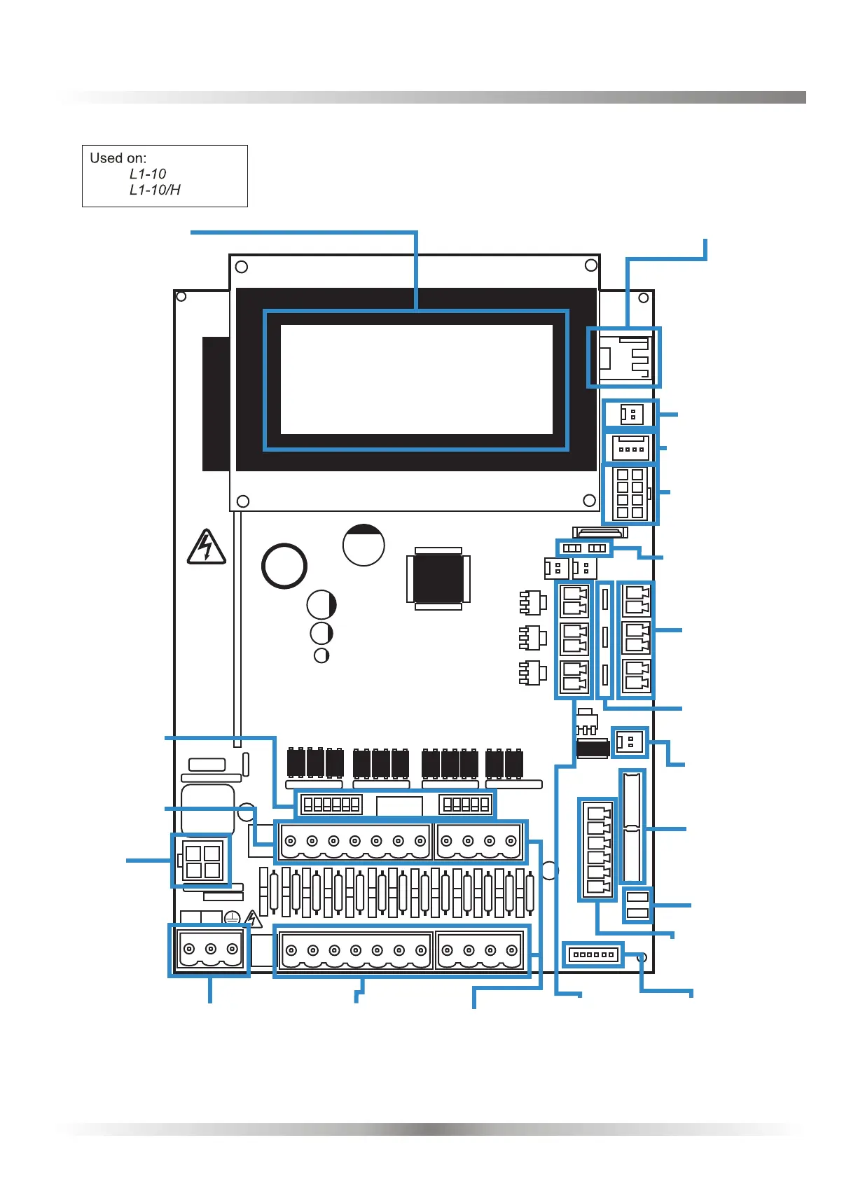
UNIT LAYOUT - MICROBOARD
Used on:
L1-10
L1-10/H
6E
-
BRIGHTLOGIC LAUNDRY SYSTEMS BRIGHTLOGIC LAUNDRY SYSTEMS
Programming
header
(for manufacturer
use only)
Supply
100V-240V AC
Connection to
keypad
Supply
indicator
lamp
(5V)&(24V)
LCD display
A Rail (Positive)
(Inputs 1-10)
B Rail (Negative)
(Inputs 1-10)
Motor output
(1 & 2)
Formula Select
Flush Valves
(x3)
Safety Stop
(x3)
Wireless USB Module
Resistor Packs
Mains out
Pump Add on
connection RS485
Isolation
Switches
(Inputs 1-10)
24V DC
Output
Safety Stop Links
(x3)
Formula Select
Lk3 and Lk4
Rs232
COMMS
Alarm output
(D)
+
-
A
RAIL
B RAIL
COMMON
COMMON
ISOLATED
B RAIL
COMMON
B
RAIL
L N
Wireless USB Module
LCD Display
24V Output
RS232 COMMS
Pump Add on
connection
RS485
Supply Indicator
Lamp (5v&24v)
Safety Stop
Connectors
(x3)
Safety Stop
Jumpers
Flush Valve
Connectors
(x3)
Alarm Output
Connector
Motor
Connectors
Formula Select
Keypad
Connector
A Rail (Positive)
(Inputs 1-10)
Power Supply
100-240v (AC)
Mains
Out
B Rail (Negvative)
(Inputs 1-10)
Isolation Switches
(Inputs 1-10)
LK3 & LK4
Auto
Formula
Select
(AFS)