28 Elan 10 2.0 / Elan 16 2.0 / Elan 25 2.1 Revision D
&KDSWHU(OHFWULFFRQQHFWLRQVDFFHVVRULHV
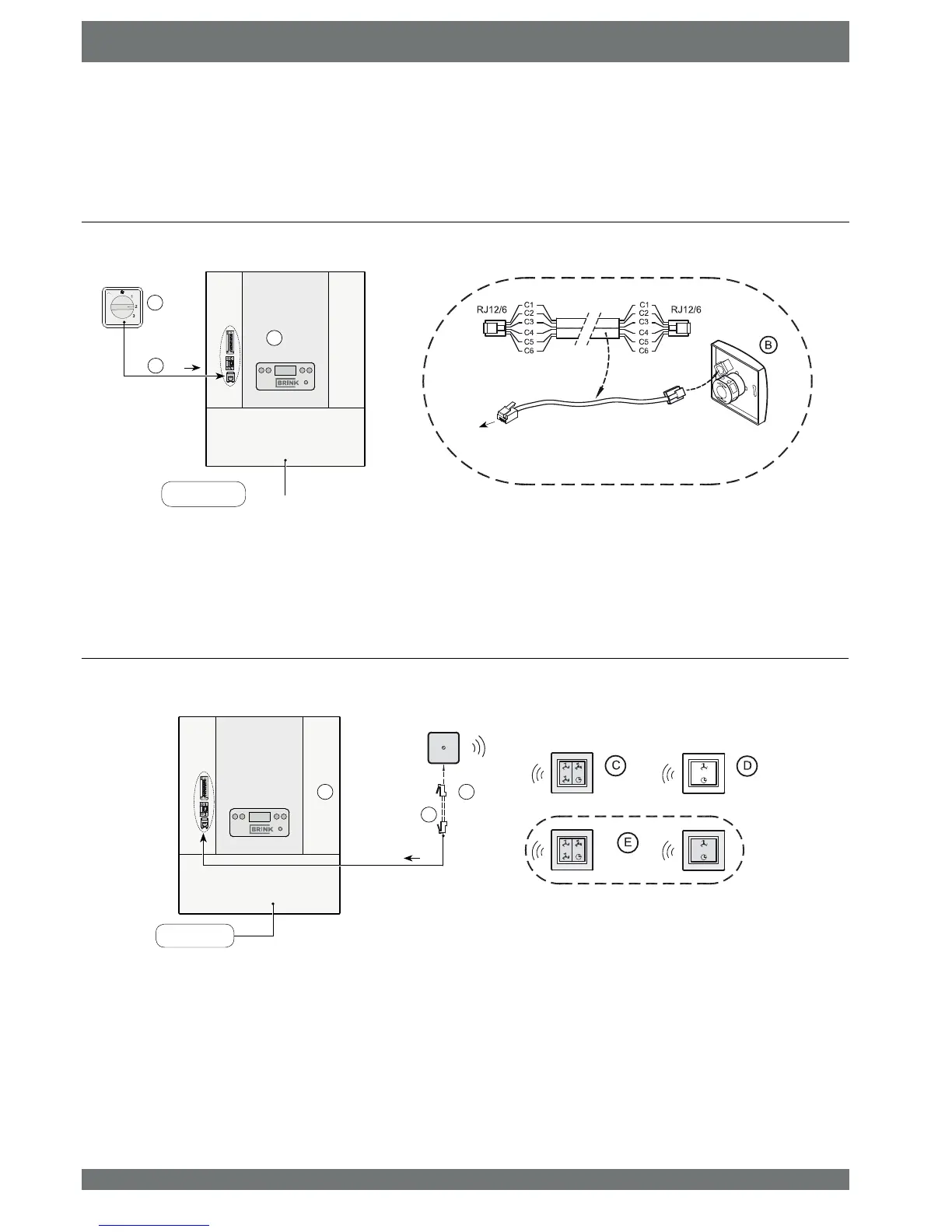
11.2 Connection examples multiple switch
Note: For the modular cable used, the “tab” of both modular connectors
must be mounted facing the mark on the modular cable.
A = (Oan appOiance
B = Receiver for ZireOess remote controO
C = Transmitter ZitK 4 settings
D = Transmitter ZitK 2 settings
( = Any additionaO 2 or 4settings transmitters (A maximum of 6 transmitters can Ee signed on to 1 receiver
) = 0oduOar caEOe 6core
A multiple switch can be connected to the modular connector X2 of the Elan appliance. This modular connector X2 can be accessed
DIWHURSHQLQJWKH¿OWHUGRRU&DEOHVFDQEHJXLGHGRXWRIWKHDSSOLDQFHWKURXJKRQHRIWKHEUHDNRXWWDEVRIWKHDSSOLDQFH
0XOWLSOHVZLWFKZLWK¿OWHULQGLFDWLRQ
A = (Oan appOiance
B = 0uOtipOe sZitcK ZitK ¿Oter indication
C = 0oduOar caEOe 6core
:LUHOHVVUHPRWHFRQWUROZLWKRXW¿OWHULQGLFDWLRQ
R
+
-
menu
230V 50Hz
A
B
C
X2
X2
1234
5
678
9
12
Wire colours C1 - C6 may vary dependent on
the type of modular cable used.
R
+
-
menu
230V 50Hz
A
B
X2
F
1234
5
678
9
12
 Loading...