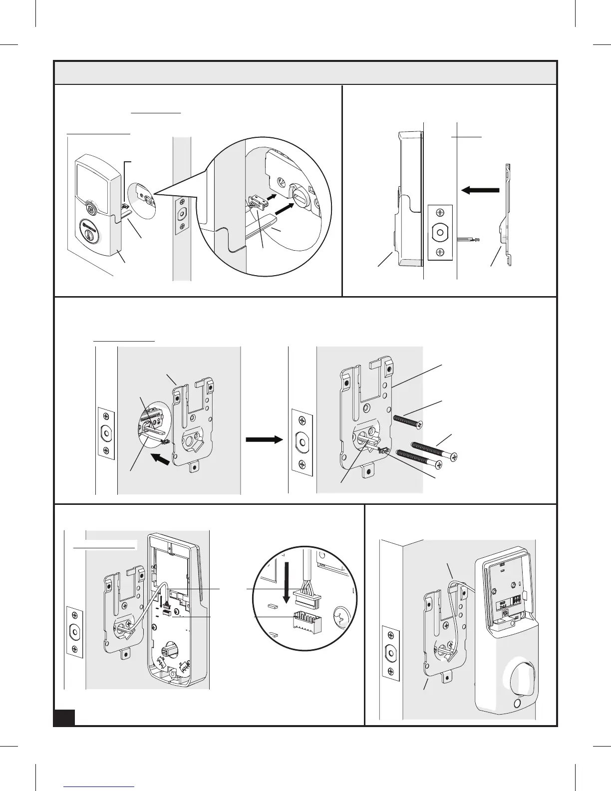
F.
Door
Interior
Mounting Plate (H)
Tailpiece (D)
Power
Cable (E)
Exterior
Assembly (B)
Bulged part of the Interior Mounting Plate (H)
must be toward the door.
Power Cable (E) goes underneath the latch. Insert
Tailpiece (D) horizontally.
E.
Tailpiece
(C)
Power
Cable (E)
E.
F.
EXTERIOR VIEW
5. Install Lock Assemblies (Continued)
Exterior
Assembly (B)
7
H.
Install the Power Cable (E) firmly into the Connector Port.
I.
Secure the Power Cable (E) onto the
Interior Mounting Plate (H) as shown.
G.
Interior Mounting
Plate (H)
Mounting
Screws (AA)
Feed Power Cable (E) through Interior Mounting Plate (H) as shown. Insert Mounting Screws (AA) and
Mounting Plate Screw (BB) as shown and tighten.
Power
Cable (E)
Tailpiece (D)
Mounting Plate
Screw (BB)
Power
Cable (E)
Interior
Mounting Plate (H)
INTERIOR VIEW
Tailpiece (D)
H.
Power
Cable (E)
Connector
Port
INTERIOR VIEW
H.
Power
Cable (E)
Interior
Mounting
Plate (H)
I.
G.