L-1523-BH1-C8
================================================================================================
English Manual
ASSEMBLY
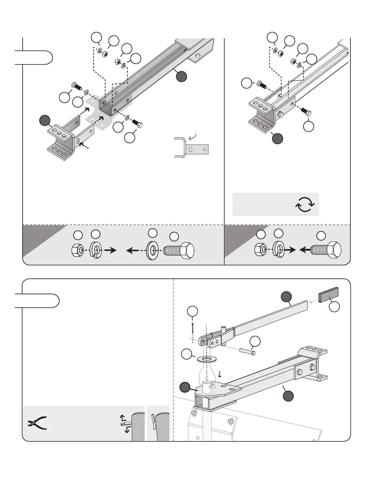
Step 4
19
11
15
18
- Add the drawbar (10) to the blade mount
plate post (7) as illustrated. Follow with the large
at washer (1).
- Slide the handle grip (6) on the end of the
angling lever (4), then align it on the mount
plate post (7) as illustrated.
- Insert the 7/16" x 2-3/8" Shear pin (5) through
the round holes at the end of the lever and post.
Secure with the 1/8" x 1" cotter pin (20).
Align the Hitch Assembly (9) with the Drawbar (10) as illustrated
here. Add a at washer (19) to two 1/2" x 1-1/4" Hex Bolts (11) as
shown. Run the bolts through the rst holes of the hitch assembly
and drawbar.
Add a Lock Washer (18) and nut (15) to each bolt.
Do not tighten fully (YET).
Run two 1/2" x
1-1/4" Hex Bolts (11) through the hitch
assembly and drawbar, as illustrated.
Add a Lock Washer (18) and nut (15) to
each bolt. Do not tighten fully (YET).
Step 5-A
5
1
20
10
4
6
7
9
10
19
11
11
15
15
18
18
19
9
11
15
15
18
18
11
NOTE: Bend the
cotter pin (20) ends as
illustrated to secure.
11
15
18
Note: Slightly
longer edge
points up.
NOTE: Flip drawbar
over for next step.