8 L-1681BH-MEnglish Manual
1
1
5
5
12
8
8
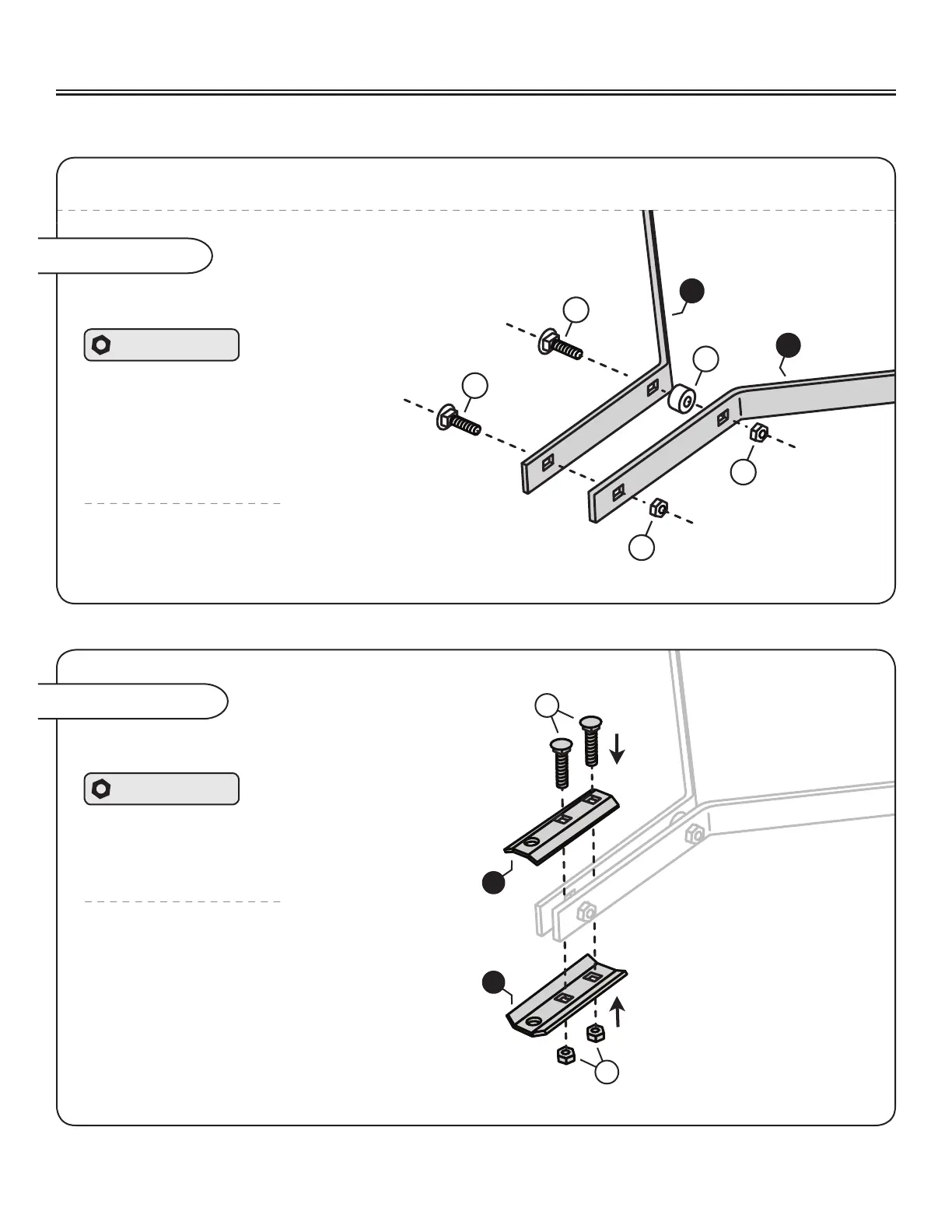
NOTE: Do not tighten the lock nuts added on this step completely (until Assembly Step 4-A is complete).
Assembly Step 3
Connecting the Frame Extension Bars
Center the Spacer (12) between the second
hole of the Extension Bars (1) and run a
5/16” Carriage Bolt (5) through.
Loosely add a 5/16” Lock Nut (8).
Hardware Panel C
Add the second 5/16” Carriage bolt to
the Extension Bars (1) and secure with
the additional 5/16” Lock Nut (8).
Assembly Step 4
Align the Clevis plates (20)
as illustrated.
NOTE: The two bolts that will be added on
this step need to straddle the Carriage Bolt
at the very end of the extension bars.
Run two 5/16 x 2-1/4” Carriage
Bolts (6) through the Clevis Plates (20).
Secure in place with two 5/16” Nylon
Lock Nuts (8).
Hardware Panel D
Attaching the Clevis
20
20
6
8
ASSEMBLY
 Loading...