21
EN
Production code lter cartridge – example: B9224350010
9 Production year, this example:2019
22 Production week, this example: calendar week 22
4 Production day from Monday(1) to Friday (2), this example: Thursday
35 Internal Identication No. of lter medium this example: No. 35
0010 Consecutive number of the lter cartridge, this example the tenth cartridge; reset the day changes
3.5 Technical Safety Assembly Instructions
• The appliance in which the lter is used must be free of limescale and gypsum deposits prior
to installation.
• Protect the lter system from sunlight and mechanical damage. Do not assemble near sour-
ces of heat and open ames.
• A stop valve must be installed before the lter system inlet hose.
• If the water pressure is greater than 8.6 bar, a pressure reducer must be installed in front of
the lter system.
• When choosing the material for parts that come into contact with water after the BRITA lter
system, it is important to remember that, due to the process, decarbonised water contains
free carbon dioxide. For this reason, only materials that are compatible with free carbon dioxide
must be used. We recommend the use of BRITA hoses.
• All parts must be installed in accordance with the country-specic guidelines on the installation
of drinking water facilities.
4 Installation
!
Caution: Prior to installation, read the technical data (Chapter 9) and the operating and safety
information (Chapter 3). After storage and transport below 0 °C, the product must be stored in the open
original packaging for at least 24 hours before it is commissioned at the stated ambient temperatures
(Chapter 9) for operation.
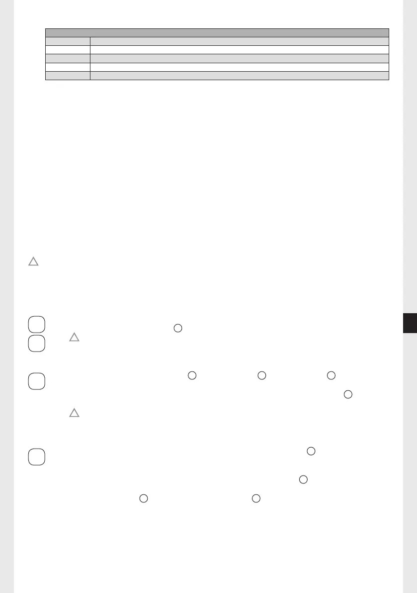
4.1 Assembling the lter head, water connection
A
B
• Close the water intake and switch off the power supply to the end device
• Fit the wall mounting bracket
5
in the intended position.*
!
Caution: When tting the bracket, note the installation dimensions, bending radii of
the hoses and dimensions of the accessories (e.g. BRITA FlowMeter). When using the
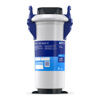
wall mount, install vertically only! The PURITY C1100 cannot be installed using the wall
mounting bracket.
C
• Fit the hoses to the water inlet “IN”
4
and outlet “OUT”
3
on the lter head
1
.
• Use at seals for G3/8” connections. For John Guest connections, use hoses with
a diameter of 8 mm. In the case of John Guest connections, the two safety clips
12
must
be inserted after tting the hose.
!
Caution: The tightening torque at G3/8” connections must not exceed 14 Nm!
Only hose connections with at seals may be used, as hoses with conical screw
connections damage the connections on the lter head and invalidate any warranty
claim! We recommend the use of BRITA hoses.
D
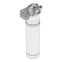
• When using PURITY C 0–70 % lter heads, check by-pass setting
10
(set to 30 % at
the factory) and if necessary adjust this setting to the local carbonate hardness
(PURITY C Quell ST) (chapter 4.2).
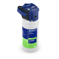
• When using PURITY C Steam lter heads, check by-pass setting
10
(set to 1 at the factory)
and if necessary adjust this setting (chapter 4.2).
• Lock the lter head
1
in the wall mounting bracket
5
.
* PURITY C Steam lter head is delivered without wall mounting bracket.


 To Next Page