9
4.4 Flue Terminal Clearances
Heaters should be positioned so that when measured from the edges of the flue the following minimum clearances
exist.
75mm
• From the wall against which the heater is mounted.
• From a drain or soil pipe.
300mm
• From a flue terminal, cowl or combustion air intake.
• Below eaves, balconies or other projections.
• From the ground, above a balcony or other surface.
• To a return wall o
r external corner.
• Measured horizontally, from an opening window, door, non-mechanical air inlet or any other opening into the
building (except sub floor ventilation) or 1500mm in direction of discharge.
500mm
• From an electricity meter or fuse box (prohibited area extends to ground level).
1000mm
• Measured vertically, from an opening window, door, non-mechanical air inlet or any other opening into the
building (except sub floor ventilation).
• From a gas meter.
• From a mechanical air inlet, including a spa blower, measured both vertically and horizontally.
• A flue terminal of this type shall not be located under a roofed area, unless the roofed area is fully open on at
least two sides, and a free flow of air at the appliance is achieved.
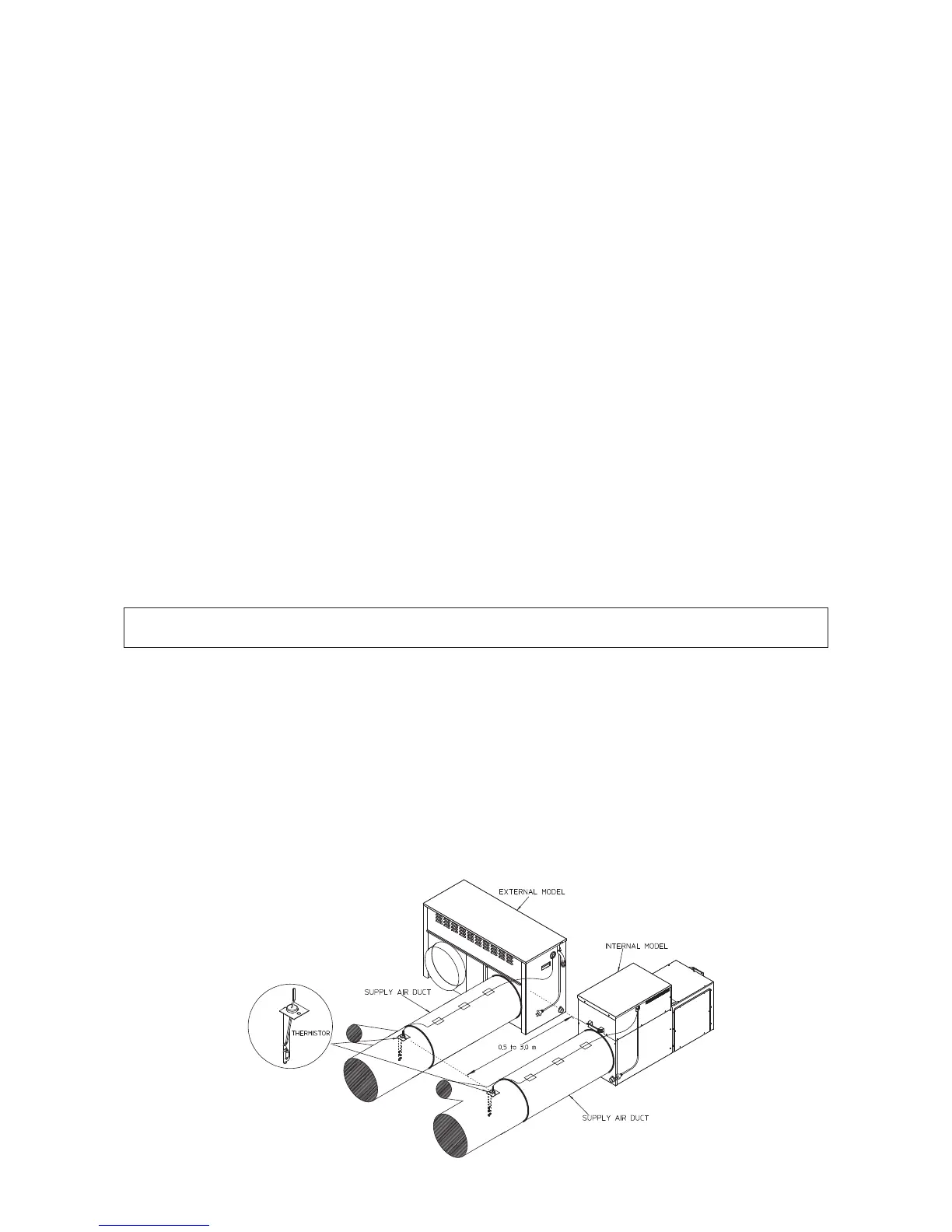
5. StarPro Max/Plus & B-Max
Installation of Thermistor
All StarPro Max/Plus & B-Max heaters are supplied with a remote thermistor assembly. The thermistor must be installed
in the supply air duct, between 0.5 to 3m away from the heater, but never beyond the first branch take off (BTO)
fitting.
These installation practices promote more accurate supply air temperature control and optimise heater performance.
• Ensure that there is at least 500mm of appropriatel
y sized ducting installed between the heater and the first BTO
fitting (or evaporator coil).
• Drill a 20mm diameter hole through the top of the inlet end of the first BTO fitting (see diagram below) or
through the top of the evaporator coil’s inlet pop.
• Carefully insert the thermistor assembly (probe end first) into this hole and secure using the self drilling screw
provided. Seal any remaining open
ings with duct tape.
• Ensure that the thermistor lead is secured to timbers or duct outer casing (see diagram) to prevent damage.
Where the first BTO fitting or the evaporator coil are installed more than 3m away from the heater, an additional
duct joiner (installer supplied) will be required so that the thermistor assembly can be fitted correctly. Install the joiner
between 0.5 to 3m away from the heater ensuring that the thermistor can reach this joint. Then follow the steps above
as per normal practice.
MX Illustrated
Note: Where an Add-On air conditioning evaporator coil is installed, the thermistor must be located in the
discharge pop of the indoor coil.
 Loading...