281 Issue 1 - Service Manual - BX3
9
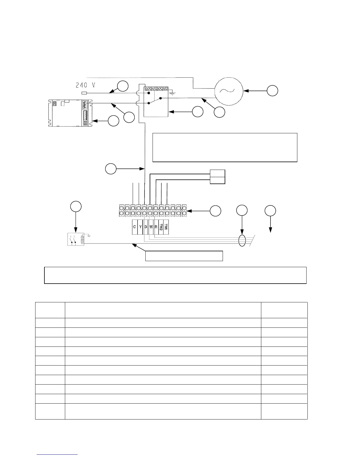
Wiring the Brivis Programmable Thermostat (Add-On & Fan Only)
The BX3 does control board does not have provision for “Add-On” cooling. For “Add-On”
cooling operation the unit can be configured. Refer to Diagram 5 for interconnection to the unit
and wall control for “Add-On” cooling.
For heating only systems “Fan Only” operation can be configured as shown in Diagram 5, the
only connection not required is “Y”.
Diagram 5.
Item
No:
Description Field Supplied
Y/N
1 ¼” spade (female) + cover + sheathed conductor 0.75mm² (min) Y
2 Fan Motor N
3 Red conductor N
4 Relay NC - 24Vac coil switching 240Vac Y
5 Heater Control Board N
6 CDU Compressor Relay Y
7 Sheathed conductor wire, minimum 0.75mm² cross-sectional area Y
8 Sheathed conductor wire, minimum 0.75mm² cross-sectional area Y
9 Terminal block on Heater N
10 Brivis Programmable Controller Purchase
from Brivis
Notes:
1. All electrical works to comply with relevant regulations.
2. Requires Brivis programmable Thermostat.
3. For field supplied parts refer to Table 2.
On the heater terminal block ‘C’ (Blue), ‘Y’ (Gray), ‘TW2’ (Orange) & ‘TW1’ (Black) are all inactive