1. Choose the location for your fan/light in the ceiling. For
best possible performance, use the shortest possible
duct run and a minimum number of elbows.
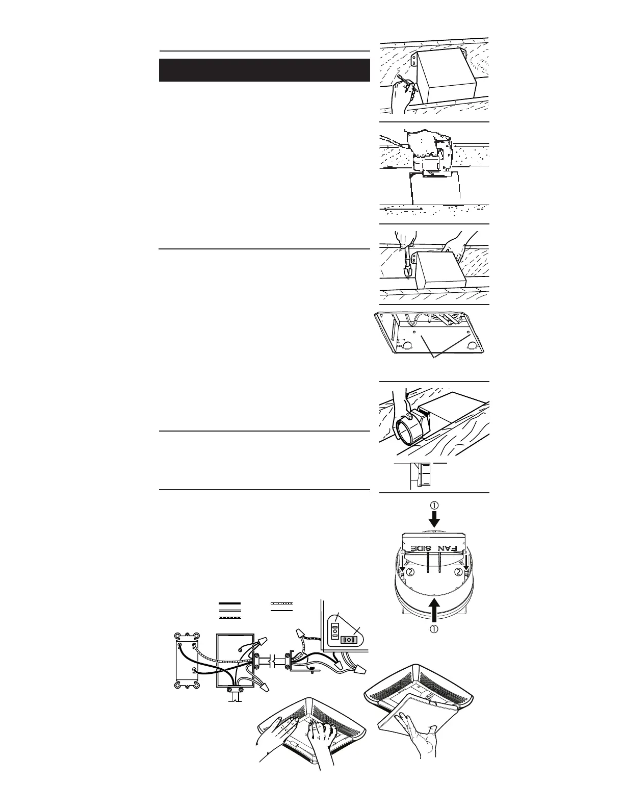
2. In attic, position mounting brackets against joist. Trace
outline of housing on ceiling material.
3. Set housing aside and cut ceiling opening slightly larger
than marked.
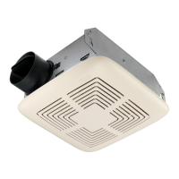
4. Place housing in opening so that its bottom edge is flush
with finished ceiling. Nail to joist through keyhole on both
sides. To ensure a noise-free installation, drive another
nail through the top hole of each mounting bracket.
5. Additional mounting holes are provided for installations
where access from above is inconvenient or not possible.
Nail or screw housing directly to joists or framing.
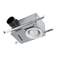
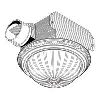
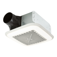
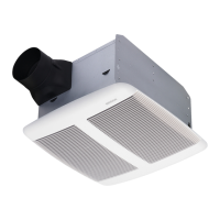
INSTALL THE HOUSING
INSTALL THE DUCTWORK
NOTE: The duct connector has a counter-balanced damper flap.
The flap will be “open” approx. 1” when duct connector is at-
tached to housing. This design permits insulation to be in direct
contact with fan/light housing per UL (Underwriters Laboratories)
standards. The slightest backdraft, however, will close the damper
flap, preventing air from entering unit or finished space.
1. Snap the damper/duct connector onto housing. Make sure
that tabs on the connector lock into slots in housing. Top of
damper/duct connector should be flush with top of housing.
NOTE: Make sure damper flap is in place inside of duct con-
nector. If it is not:
Squeeze top and bottom of connector
to
snap flap back into place.
2. Connect 4” round duct to damper/duct connector and extend
duct to outside through a roof or wall cap. Check damper to
make sure that it opens freely. Tape all duct connections to
make them secure and air tight.
Existing Construction
SWITCH BOX
LIGHT
FAN
DUAL CONTROL
(purchase separately)
WHITE
BLACK
RED
GROUND
(bare)
WIRING
PLATE
120 VAC
LINE IN
BLUE
BLACK
RECEPTACLE
(FAN)
WHITE
RECEPTACLE
(LIGHT)
CONNECT THE WIRING
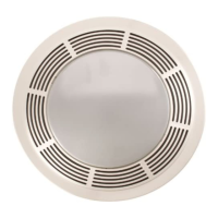
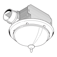
1. Slide light reflector into front of grille opening. Plug light
into WHITE receptacle. Place grille / reflector combination
over protruding screw, and fasten in place using acorn nut
provided. HAND TIGHTEN acorn nut 1/4 turn after it is snug.
NOTE: If grille and light reflector are not snug to ceiling, use
a nut driver or pliers on acorn nut to snug grille to ceiling.
2. Install light bulb (not included). (See next page for type
and size for your model.) Insert one tab on light lens into
a slot in the grille / reflector combination. Squeeze other
tab slightly and snap into remaining slot.
ATTACH THE GRILLE
1. Wire unit following diagram. Run electrical cable as direct
as possible to unit. Do not allow cable to touch sides or
top of unit after installation is complete.
ADDITIONAL MOUNTING HOLES
FLUSH