!
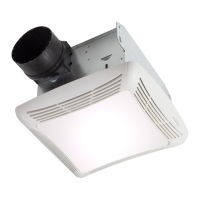
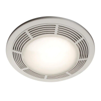
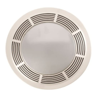
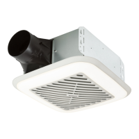
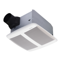
FAN/LIGHT COMBINATION VENTILATOR
MODEL 763 • 763N
WARNING
TO REDUCE THE RISK OF FIRE, ELECTRIC
SHOCK, OR INJURY TO PERSONS, OBSERVE
THE FOLLOWING:
1. Use this unit only in the manner intended by the
manufacturer. If you have questions, contact
the manufacturer at the address or telephone
number listed in the warranty.
2. Before servicing or cleaning unit, switch power
off at service panel and lock the service discon-
necting means to prevent power from being
switched on accidentally. When the service dis-
connecting means cannot be locked, securely
fasten a prominent warning device, such as a
tag, to the service panel.
3. Installation work and electrical wiring must be
done by a qualified person(s) in accordance
with all applicable codes and standards, includ-
ing fire-rated construction codes and standards.
4. Sufficient air is needed for proper combus-
tion and exhausting of gases through the flue
(chimney) of fuel burning equipment to prevent
backdrafting. Follow the heating equipment
manufacturer’s guideline and safety standards
such as those published by the National Fire
Protection Association (NFPA), and the Ameri-
can Society for Heating, Refrigeration and Air
Conditioning Engineers (ASHRAE), and the local
code authorities.
5. When cutting or drilling into wall or ceiling, do
not damage electrical wiring and other hidden
utilities.
6. Ducted fans must always be vented to the
outdoors.
7. If this unit is to be installed over a tub or shower,
it must be marked as appropriate for the appli-
cation and be connected to a GFCI (Ground Fault
Circuit Interrupter) - protected branch circuit.
8. Never place a switch where it can be reached
from a tub or shower.
9. This unit must be grounded.
CAUTION
1. For general ventilating use only. Do not use to
exhaust hazardous or explosive materials and
vapors.
2. This product is designed for ceiling installation
only. This product is designed for installation
in ceilings up to a 12/12 pitch. Ductwork must
point up. DO NOT MOUNT THIS PRODUCT IN
A WALL.
3. To avoid motor bearing damage and noisy and/
or unbalanced impellers, keep drywall spray,
construction dust, etc. off power unit.
4. Please read specification label on product for
further information and requirements.
Installer: Leave this manual with the
homeowner. Homeowner: Use and Care
information on page 4.
READ AND SAVE
THESE INSTRUCTIONS
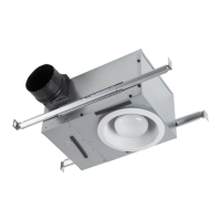
TYPICAL INSTALLATIONS
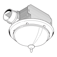
HOUSING
CEILING
JOIST
MOUNTING TABS
GRILLE
CEILING
MATERIAL
POWER CABLE
HOUSING
CEILING
JOIST
MOUNTING TABS
GRILLE
CEILING
MATERIAL
POWER CABLE
4" ROUND
DUCT
ADDITIONAL
FRAMING
HOUSING MOUNTED TO ADDITIONAL FRAMING
Discharge 90
0
to joists.
HOUSING MOUNTED DIRECTLY TO JOIST
2x6 (or larger) Discharge parallel to joists.
HOUSING
2 x 4
CEILING
JOIST or
TRUSS
MOUNTING
TABS
CEILING
MATERIAL
POWER CABLE
ADDITIONAL
FRAMING
2 x 4
CEILING
JOIST or
TRUSS
GRILLE
HOUSING MOUNTED TO 2x4 TRUSS
Requires additional framing for mounting tabs.
Discharge parallel to joists.
HOUSING
MOUNTING
TABS
CEILING
MATERIAL
POWER CABLE
ADDITIONAL
FRAMING
"
I
"
JOIST
"
I
"
JOIST
GRILLE
HOUSING MOUNTED TO “I” JOIST
Requires additional framing for mounting tabs.
Discharge parallel to joists.
HOUSING
2 x 4
CEILING
JOIST or
TRUSS
MOUNTING TABS
CEILING
MATERIAL
POWER CABLE
4" ROUND
DUCT
ADDITIONAL
FRAMING
2 x 4
CEILING
JOIST or
TRUSS
GRILLE
HOUSING MOUNTED TO 2x4 TRUSS
Requires additional framing for mounting tabs.
Discharge 90
0
to joists.
HOUSING
MOUNTING TABS
CEILING
MATERIAL
POWER CABLE
4" ROUND
DUCT
ADDITIONAL
FRAMING
"
I
"
JOIST
"
I
"
JOIST
GRILLE
HOUSING MOUNTED TO “I” JOIST
Requires additional framing for mounting tabs.
Discharge 90
0
to joists.
* Additional framing must be a 2x6 (minimum height).
*
*
*
*
*