PLANNING -.(continued) PLAN THE DUCTWORK
Note: The high level of air flow of this appliance may affect the gas
flame on some types of gas cooktops. This is NORMAL and wilt
cause no harm, but can be corrected by lowering the speed of the
blower.
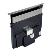
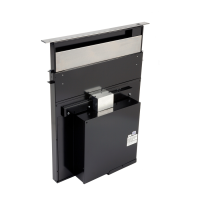
SPECIFICATIONS
_DISCHARGE i
3-1/4x lol
Install downdraft with an exterior blower that draws 6.0 AMPS or
less.
TAKE MEASUREMENTS
1.
2.
Refer to the cooktop installation instructions for dimensions of
cooktop, countertop cut-out, and cabinet requirements. The
Model 2830 will fit in most 30" wide cabinets and the Model
2836 will fit in most 36" wide cabinets. However, it is recom-
mended that oversized cabinets be used for easier installa-
tion.
Cooktop depth can vary greatly from one to another. This may
cause the fit of these two appliances to be rather tight.
FRONT TO SACK
iNSiDE CABINET DEPTH
Pay special attention to the areas of potential interference high-
lighted above. A countertop with (A) a raised lip and/or (B) a
backsptash may not allow enough flat countertop for a proper
installation. Note that 2" of flat countertop is required behind
cooktop and that 1-3/4" is necessary between the back edge of the
cooktop and the inside of cabinet back.
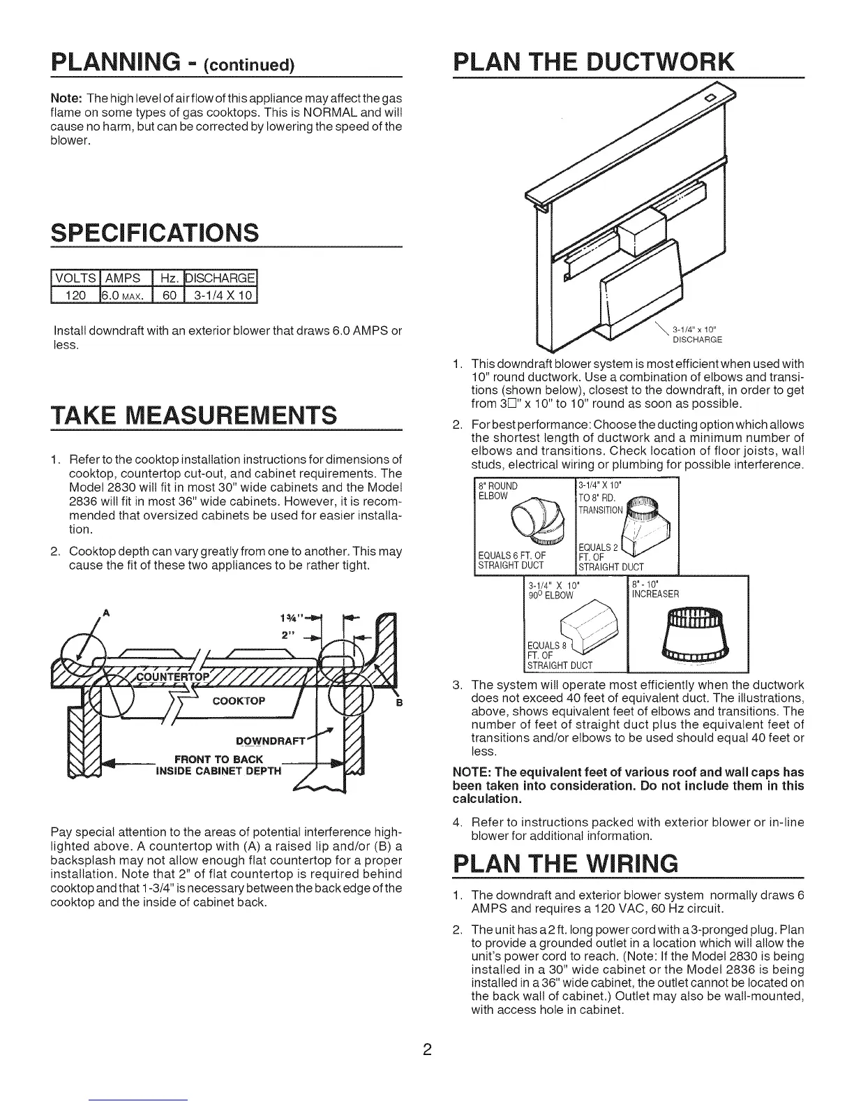
_ 3-1/4" x 10"
DISCHARGE
1.
2.
This downdraft blower system is most efficient when used with
10" round ductwork. Use a combination of elbows and transi-
tions (shown below), closest to the downdraft, in order to get
from 3F]" x 10" to 10" round as soon as possible.
For best performance: Choose the ducting option which allows
the shortest length of ductwork and a minimum number of
elbows and transitions. Check location of floor joists, walt
studs, electrical wiring or plumbing for possible interference.
8" ROUND 3-1/4" X 10"
I EQUALS2 I,_ I J
EQUALS6 FT. OF _FT.OF
I STRAGHT DUCT !STRAIGHT DUCT
3-1/4" X 10"
90o ELBOW
-.<
EQUALS_
I FT. OF --
STRAIGHTDUCT
18"- 10"
INCREASER
3. The system will operate most efficiently when the ductwork
does not exceed 40 feet of equivalent duct. The illustrations,
above, shows equivalent feet of elbows and transitions. The
number of feet of straight duct plus the equivalent feet of
transitions and/or elbows to be used should equal 40 feet or
less.
NOTE: The equivalent feet of various roof and wall caps has
been taken into consideration. Do not include them in this
calculation.
4. Refer to instructions packed with exterior blower or in-line
blower for additional information.
PLAN THE WIRING
1.
2.
The downdraft and exterior blower system normally draws 6
AMPS and requires a 120 VAC, 60 Hz circuit.
The unit has a 2 ft. long power cord with a 3-pronged plug. Plan
to provide a grounded outlet in a location which will allow the
unit's power cord to reach. (Note: If the Model 2830 is being
installed in a 30" wide cabinet or the Model 2836 is being
installed in a 36" wide cabinet, the outlet cannot be located on
the back walt of cabinet.) Outlet may also be walt-mounted,
with access hole in cabinet.
2